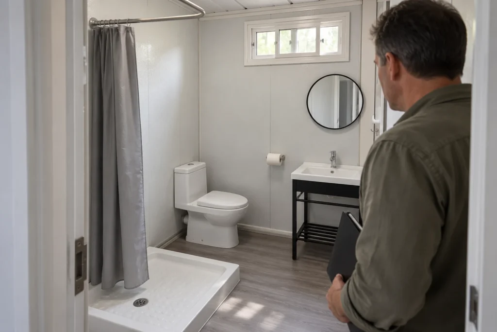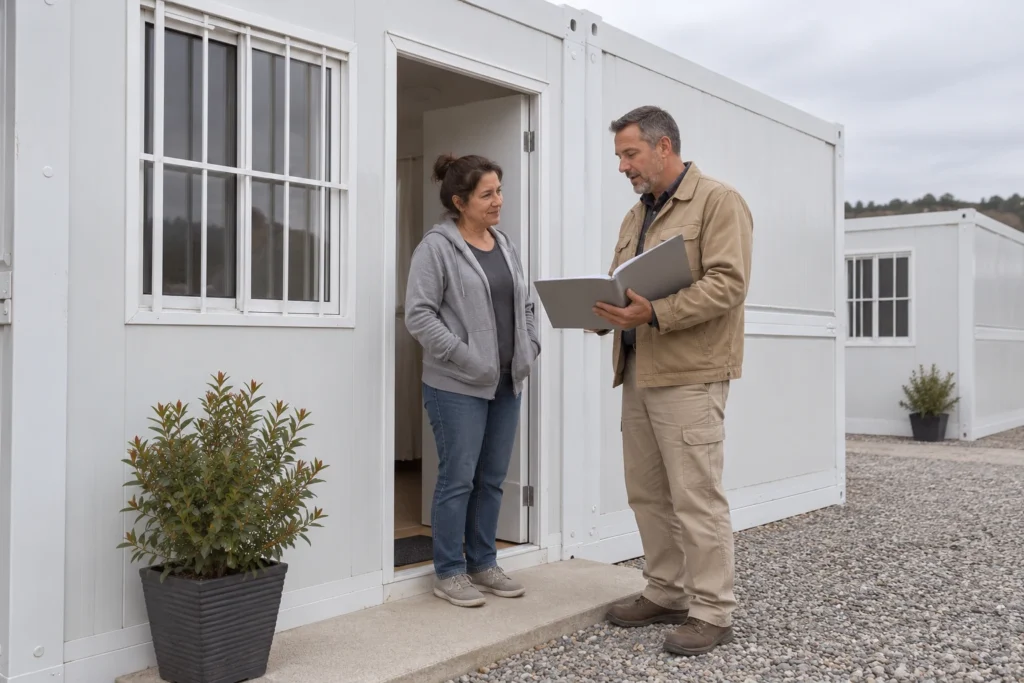
An expandable container house is not weather-ready simply because both wings have opened and the interior looks finished. Deployment creates or exposes roof, wall, floor and opening interfaces that must form a continuous route for rainwater to leave the building. A small gap, compressed seal in the wrong place, reversed flashing or blocked drain may be invisible in a dry-day photograph. Buyers and site teams need a model-specific inspection and an agreed response to water found inside.
This article covers the inspection after an expandable unit has been set up and before handover, plus checks after later movement or heavy weather. It is not a universal installation sequence or a substitute for the manufacturer’s drawings and local professional review. The PQSE expandable container house can be configured for different projects; request the selected model’s joint, seal, roof and drainage details before assessing it. Avoid importing another manufacturer’s sealant, torque, roof trim or test pressure into the job.
Read the approved water path before looking for a leak
Start with the envelope drawing. Identify the intended outer shedding surface, the joint details, flashings or covers, drainage outlets, windows, doors and service penetrations. Ask how water should travel from the roof to the wall and then away from the base. A joint should be judged in that path, not only by whether a bead of sealant looks neat. The U.S. Department of Energy’s common flashing guidance explains a broad principle: layered details should direct rain down and outward, especially where water-control layers end or are interrupted. Its examples are conventional buildings, so the supplier’s actual expandable-unit detail controls the specific assembly.
Mark the interfaces created by opening the unit. A typical inspection route may include the central roof-to-wing connection, roof corners, wing wall-to-core joints, wall-to-floor line, window and door openings, roof or wall service penetrations and the lower edge near the supports. The selected product may use a different geometry. Draw a simple elevation and number each inspection location so photographs, test notes and corrections can be tied to the same place. “Leak at side” is not enough for a repair team.

The container house quality-control guide helps separate factory inspection from field verification. A factory check can demonstrate the manufactured component’s condition, but the final open-state envelope depends on transport condition, support, alignment, site assembly and added services. Put both sets of evidence in the handover file. A factory water test does not automatically prove that a later deployment, roof penetration or repaired seal remains sound.
Distinguish a water-shedding detail from a decorative cover
Ask what the exterior trim actually does. A cover may protect a seal from weather or direct runoff; an interior skirting piece may only hide a gap. Do not assume that an attractive trim hides a complete water-control layer. The drawings should show the relationship of cover, gasket or seal, fastening, movement allowance and the exit route for any water that reaches behind the first line. If the installer cannot identify the detail or a supplied component is missing, record a hold point before occupancy.
Building Science Corporation’s water management research makes a useful distinction between excluding every drop at the outer face and draining incidental water back outside. It cautions against relying only on sealants and gaskets at component joints. Apply that as a diagnostic question, not as proof that a particular PQSE configuration has a drainage cavity: where would water go if the outer seal aged or a joint moved? Only the approved unit detail can answer.
Check the unit’s support and final geometry first
Before examining seal quality, confirm the foundation or support condition, expanded position and locking state against the manufacturer documents. The roof and wall connections may appear sealed while the unit is twisted, incompletely supported or not fully locked. Misalignment can change seal compression, create an unintended slope and stress a joint during later use. The competent installer checks dimensions and hardware; a buyer should ask for the recorded results, not infer them from a level-looking interior floor.
If a door starts rubbing after rain or the wing floor has changed height relative to the core, do not automatically treat it as a door-adjustment problem. Support movement or panel geometry can alter both operation and water resistance. Compare the current measurements with the accepted baseline, inspect drainage and refer structural concerns to the responsible professional. A bead of added sealant cannot correct a changing geometry. The general installation guide explains why site support, assembly and final checks are connected stages.
Where the unit is relocated, repeat the checks. A seal that performed at the first location may be disturbed by folding, transport, opening or a different base. Ask which seals, flashings or trims are reusable and which require replacement or rework under the actual manual. Record spare-part identity and the person authorized to reinstall it. “Relocatable” describes a project option, not a promise that every joint can be reopened indefinitely without inspection.
Protect the inspection team from moving parts
Do not lean on or enter a moving wing, work beneath an unsupported roof panel or use the water test as a substitute for confirming structural stability. The approved deployment and lifting procedure must be finished first. UMD’s expandable-house installation guide shows one supplier’s staged connections and sealing work; it is useful as a comparator because it treats waterproofing as an installation stage. Its sequence and materials are specific to UMD and should never be substituted for PQSE instructions.
Use safe access to inspect the roof. A drone or telephoto image can reveal broad trim alignment, but close inspection or any repair may need a designed access method and fall protection. The site team should state who performs that work and what evidence is sufficient before acceptance.
Inspect each joint for continuity and a route outward
Follow the roof connection from one end to the other. Look for missing or bent covers, incomplete laps, lifted edges, unsealed termination points, fasteners in the wrong location, ponding and debris that blocks runoff. A narrow opening can admit wind-driven rain even when there is no visible drip during calm weather. Photograph both the overview and the close detail with a location marker; record which side is up-slope and where runoff is meant to exit.
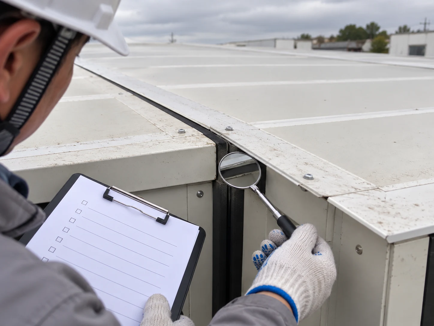
At wall and floor interfaces, check that the supplied seal or gasket is present and seated as designed. Inspect corners and transitions, where several pieces meet and a straight-line visual check can miss a gap. Look for cuts, folds, contamination, compression outside the expected range or a seal placed against a wet or dirty surface. Do not name a universal sealant type or thickness. Compatibility, surface preparation and cure requirements belong to the approved product system. If a part is missing, ask for the supplier’s replacement detail rather than improvising with a locally available tube.

At windows and doors, inspect head, jamb and sill details and where the unit’s panel system directs water. DOE window and door water-management guidance notes that openings interrupt a water-control layer and need integrated flashing. Conventional housewrap details are not directly transferable to metal-panel modules, but the question remains: does the installed opening shed or drain water outward rather than into the wall? Check the exact product detail and observe the interior reveal for staining.
Include the penetrations added after the factory
A site electrician or HVAC installer may make a new hole in a roof or wall after delivery. Each penetration changes the water-control layer. Review who approved its position, what sleeve or flashing was specified, how the seal ties into the surrounding roof or panel and who tested it. DOE’s roof penetration guide emphasizes integration with the existing water-control layer. A blob of surface sealant around a pipe may conceal an unprotected cut edge or a route behind cladding.
List every added vent, cable, pipe, bracket, canopy and awning. Where a later accessory sheds water toward a sensitive expansion joint, revise the discharge path. The responsible designer must review structural and water effects before anyone drills or fixes into an unknown panel. The warranty file should distinguish factory-supplied features from later site alterations without assuming that every later leak is caused by one or the other.
Use a controlled test and keep observations separate from guesses
Agree the test method with the supplier, installer and local professional before spraying water. State the completed construction stage, target areas, weather, water source, exposure sequence, observers and pass criteria. If the manufacturer specifies a field test, use its instructions. Do not take a hose pressure, duration or direction from a competing unit or from a conventional wall test and call it a PQSE specification. A test that overwhelms a detail in an unintended way may be misleading; a brief splash may miss a real weakness.
Start with an interior baseline. Photograph the ceiling, wall intersections, openings and floor line while dry. Protect electrical equipment and keep people clear of unsafe conditions. Observe one zone at a time, progressing in an agreed order, and note the exact moment and location of any moisture. If water appears, stop or redirect testing according to the plan, trace the likely path and document what actually happened. The interior drip point may be far from the exterior entry point, especially where water travels along a panel or fastener line.
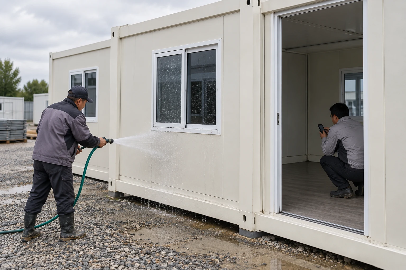
Do not treat condensation as rain leakage without evidence. Moisture on a cold interior surface can come from indoor humidity and thermal bridging; a wet pipe or plumbing fitting can imitate an envelope defect. Look at timing, weather, surface temperature, interior humidity and the path of the stain. Conversely, do not dismiss a leak as “condensation” without investigation. Record the observation and have the competent team determine the cause. The test report should state limitations, including areas not exposed and any conditions that differ from service weather.

Repair the cause, then repeat the relevant check
Set a clear disposition for every observed stain. “Monitor” can be a valid interim decision only when a named person, date, trigger and protection measure are recorded. If the room is due for occupancy, the owner should know whether the affected surface conceals insulation, wiring or a structural connection and whether drying or opening the assembly is needed. A photographed dry finish after one sunny day does not prove that hidden material is dry. The qualified team should decide whether moisture measurement, selective opening or further observation is appropriate. This is particularly important when a wall lining makes the leak path hard to see.
In the report, separate the defect from the repair method. A supplier may propose a compatible replacement seal while the site designer also needs to correct water concentration from an adjacent canopy. Closing only the visible joint may leave the driving condition in place. The recheck should reproduce the relevant exposure and verify the downstream exit path, not just inspect the new bead for neatness.
When a joint fails, record the drawing reference, observed pathway, proposed correction, responsible approver and replacement material. Photograph the original condition before removal. A failed roof-to-wing connection may need alignment correction, flashing rework, seal replacement or drainage change; another bead over the top is not automatically the right repair. After correction, recheck geometry, service penetrations and adjacent interfaces that may have been disturbed. Repeat the agreed water exposure on the affected zone and close the defect only when the specified acceptance evidence exists.
If several units show a similar symptom, compare their IDs, installation crews, part batches and support conditions. This helps distinguish a common drawing or component issue from a one-off installation error. Do not claim a systemic product defect from one wet patch, but do not repeat a repair across the fleet without understanding why it worked on the first unit.
Make drainage and the surrounding site part of the review
Water should leave the building and site without returning to the base. Check roof outlets, gutters if supplied, downpipes and discharge positions. A drain that works in a dry factory may clog with leaves or construction debris at the actual site. Verify that ground grading and splash conditions do not soak the lower wall. Where multiple units are grouped, one roof or walkway should not direct runoff onto the adjacent unit’s door, joint or foundation.
The boundary with site work matters. The building supplier can specify roof discharge points, but the civil or site designer must route water from them to a lawful destination. The container house permits and codes guide is a reminder that drainage and local approvals are project-specific. Do not discharge onto a neighbor, inaccessible walkway or electrical installation simply because the unit’s own roof is dry.
For camps and repeated buildings, add a map showing each unit’s inspection locations and runoff direction. A worker camp accommodation layout may place many wet-weather pathways close together. A leak-free single-unit demonstration does not settle the drainage interactions of a whole camp. The site team should review common walkways, covered entries, sanitary blocks and external services as a connected arrangement.
Establish an inspection cycle tied to events
Make a baseline at first acceptance, then inspect after relocation, a severe weather event, roof work, a new penetration or a reported stain. Routine checks should follow the manufacturer’s maintenance instructions and local climate. Record cracks, lifted trim, changed gaps, ponding, blocked drains, corrosion and interior moisture. Ask who may clean or replace seals and which work requires the supplier or qualified contractor. A schedule without a named owner and defect route is unlikely to protect the asset.
Keep a small stock of the approved parts only if their identity, shelf life and storage conditions can be controlled. Substituting an unknown sealant can create adhesion or compatibility problems and make later diagnosis difficult. The maintenance file should include the original detail, part codes, installation method, inspection photographs and each repair. This supports future deployments more than a vague assurance that the module is “waterproof.”
Hand over a water-control record, not a dry-day impression
The acceptance pack should contain the selected unit and drawing revision, support and lock checks, joint and penetration photos, test plan, observations, corrections, repeat checks, roof drainage map and maintenance instructions. Mark any untested areas and temporary weather protection. If a clinical or electrical use makes interior moisture particularly consequential, the operating owner may require additional tests; these should be defined before purchase.
Buyers should ask the supplier for model-specific joint details, approved seal and flashing materials, replacement conditions and a deployment inspection checklist. Ask the installer for a signed record of open-state alignment and completed weathering work. Ask the site team where the water goes after it leaves the unit. These three answers connect the physical product to its actual location.

If you are comparing expandable units, send PQSE the model, destination climate, site drainage conditions and planned number of relocations so the discussion can identify the appropriate drawings and scope. Do not use a generic online leak-fix instruction in place of the selected configuration’s technical documents.
Sources and applicability
This guide uses PQSE’s published expandable-house information, UMD’s model-specific assembly guide and KUBO’s expandable product discussion as industry comparisons, plus Building Science Corporation and U.S. Department of Energy publications for general water-management principles. The latter sources describe other building assemblies; they support the logic of drainage and flashing, not a specific PQSE joint design. Any test method, repair product or acceptance threshold must come from the project’s approved documents and responsible professionals.