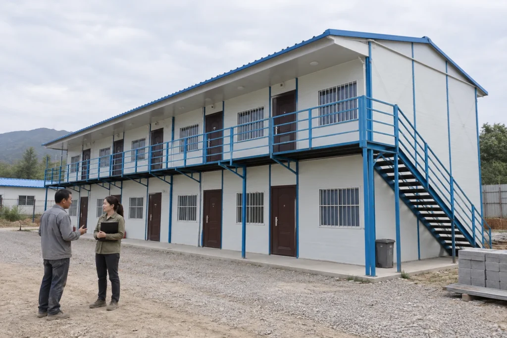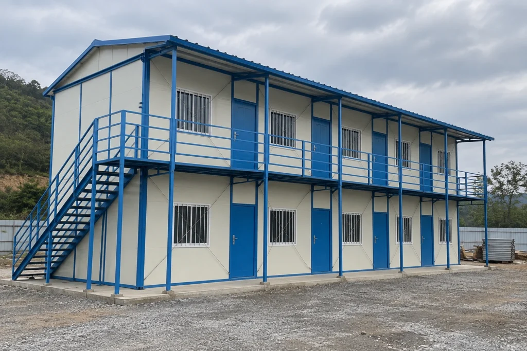
Modular building utilities should be coordinated before production drawings are released, because electrical, water, drainage, ventilation and communications systems cross the boundary between the factory module and the site. A reliable plan states the required service, design basis, load or flow, route, connection point, responsible party, test and final record for every interface. Leaving those details until installation can turn a finished module into a site redesign problem.
This guide gives project buyers a coordination method rather than a universal technical design. Loads, pipe sizes, cable sizes, protective devices, drainage falls and approval requirements must be determined by qualified professionals for the destination and intended use. Start with the appropriate container house product system and room layout, then use the process below to turn equipment choices into checkable utility interfaces.

What counts as a modular building utility interface?
An interface is a point where one system, party or construction stage hands responsibility to another. Common examples include the incoming electrical terminals, water inlet, sanitary discharge, HVAC condensate outlet, data entry point and the connection between adjacent modules. An interface also includes information: design voltage, available pressure, wastewater destination, load schedule and test requirement.
The Construction Industry Development Board Malaysia guideline for volumetric module houses includes mechanical, electrical and plumbing services interfaces as a dedicated design subject. Its jurisdiction and document scope should be respected, but its central coordination lesson is broadly useful: services need planned routes and connection points within the modular design, not improvised site penetrations.
Create an interface register as soon as the room schedule and equipment list exist. Give each interface an identifier that appears on drawings, schedules, packing lists and commissioning records. If a unit has two possible orientations, identify how that changes the connection side rather than showing one generic symbol.
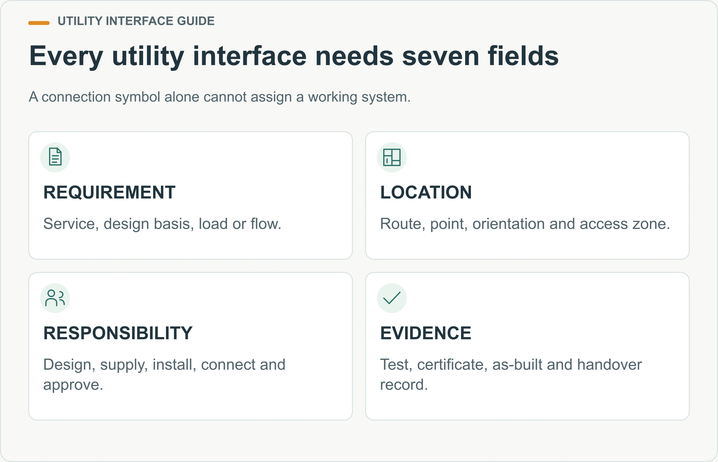
The register should distinguish permanent site utilities, temporary construction supplies and internal module distribution. A temporary generator used during installation does not prove that the permanent incoming supply is adequate. A factory water test does not prove that the site connection, pressure or wastewater route works after installation.
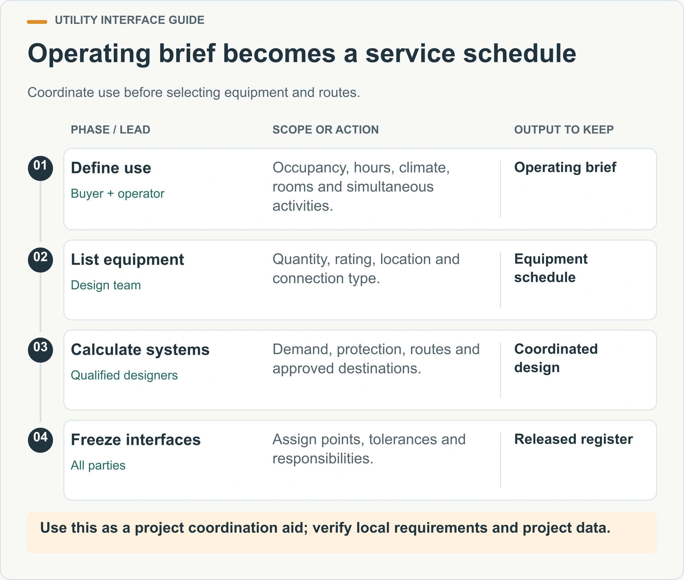
Freeze the operating brief before calculating services
Utility demand comes from how the building will be used. Record occupancy, operating hours, climate, rooms, equipment, simultaneous activities and future expansion. A site office with computers and split air conditioners has a different load pattern from accommodation with electric water heating, or a sanitation block with concentrated water demand.
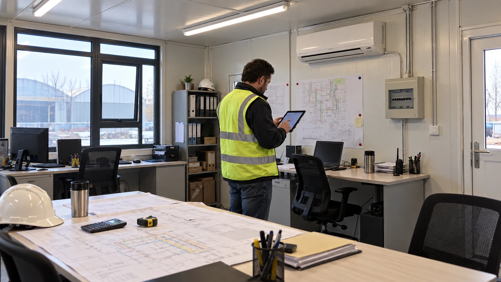
Use an equipment schedule rather than a general label. For each item, record its function, location, quantity, rated input, operating pattern, starting or peak characteristic where relevant, connection type and responsible supplier. Mark provisional items so they are not mistaken for confirmed loads.
Coordinate this work with the container house design and layout guide. Moving a bathroom, equipment room or kitchenette later can alter pipe routes, ventilation, distribution boards, wall penetrations and factory testing. Furniture can also block access to panels, valves and cleanouts.
Agree a design reserve through the responsible engineer instead of adding an unexplained percentage. The reserve should correspond to known uncertainty or planned expansion. State what it covers and whether the site supply, transformer, generator, panels and internal distribution all support it.
Which utility systems need coordinated design inputs?
Coordinate the electrical supply from source to final point
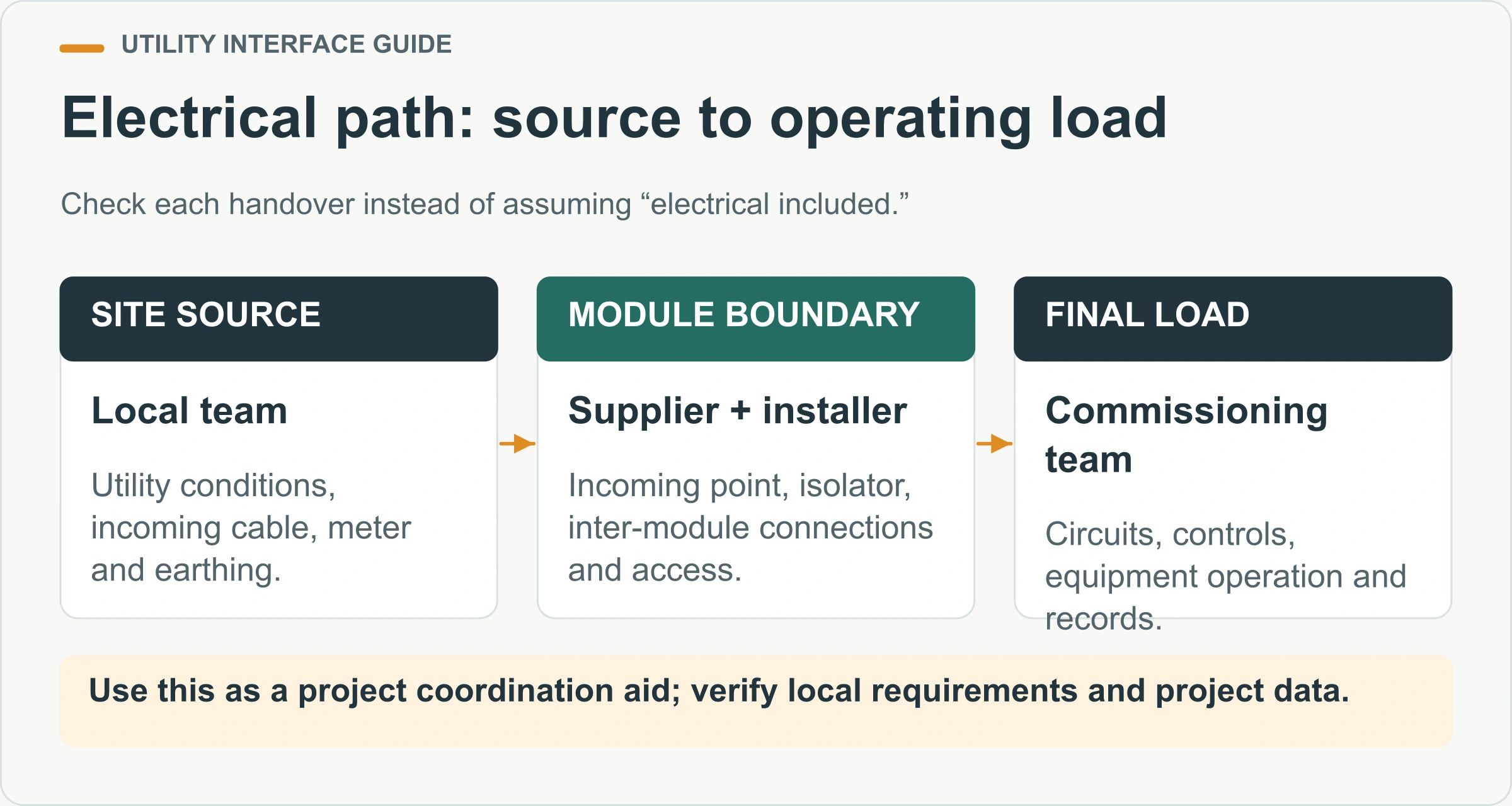
Start with the destination’s supply characteristics and local requirements: voltage, frequency, phase, earthing arrangement, available fault level and utility connection conditions. These details affect equipment selection, protective devices, distribution boards and factory tests. Do not assume that a component familiar in one market is acceptable in another.
Build a load schedule by circuit or equipment group. Separate lighting, socket outlets, HVAC, water heating, pumps, kitchen equipment, communications and specialist loads. Identify likely simultaneous use and any large starting current. The responsible designer then determines demand, distribution and protection.
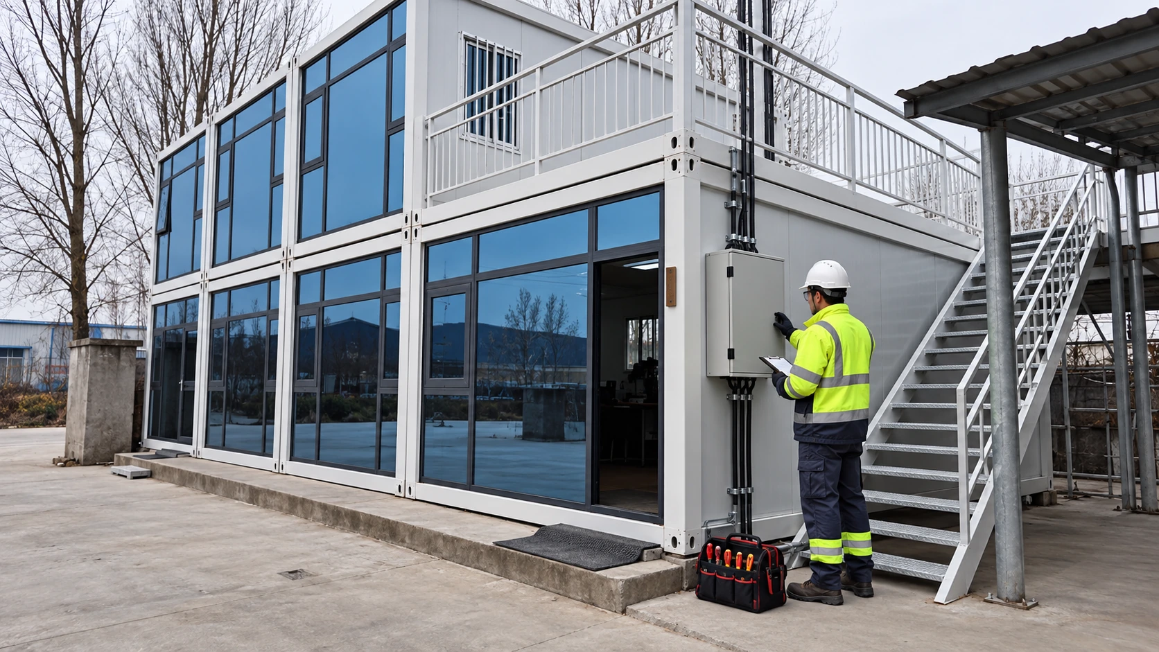
Define the incoming boundary precisely. State whether the factory supplies only internal wiring and a distribution board, or also a main isolator, external connector, meter enclosure or cable. Show the connection location, termination type, access space and weather protection. Assign supply and installation of the site cable, trench or support, gland, earthing connection and utility meter.
Module-to-module electrical connections require the same clarity. Record whether connections are plug-and-socket assemblies, terminal boxes or site-installed cables, and who verifies phase, polarity, continuity, insulation and protective measures after connection. Protect shipping ends against damage and moisture, and identify them to match the erection sequence.
Define water quantity, quality, pressure and isolation
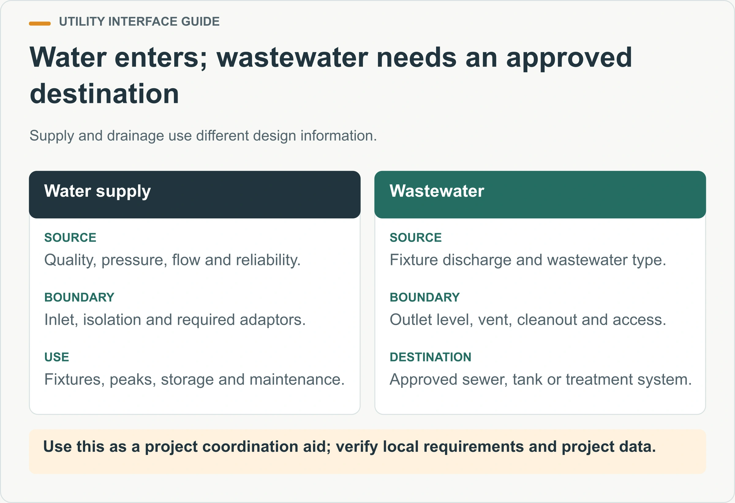
Identify the water source and the authority responsible for its quality. Record available static and operating pressure, expected flow, supply interruptions and temperature range. Equipment such as water heaters, pumps and valves must be selected from confirmed conditions rather than a generic “mains water” assumption.
List fixtures and simultaneous demand by use period. Accommodation, showers, toilets, kitchens, clinics and cleaning points have different patterns. Where stored water or boosting is considered, the responsible designer must address capacity, controls, hygiene, structural support, overflow and maintenance access.

Show the site-to-module connection point, pipe material or connection standard, isolation valve, drain point and frost or heat protection where relevant. Define who supplies flexible connectors, adaptors, filters, pressure-reducing equipment and insulation. A missing inexpensive adaptor can stop commissioning even when the complete internal system is finished.
Separate potable and non-potable systems and label them under applicable requirements. Avoid cross-connections. If reclaimed or process water is proposed, give the local designer the source, quality and intended uses so that separation, signage and backflow protection can be designed correctly.
Treat drainage as a route to an approved destination
A drain point on a drawing is only the start. Confirm the wastewater type, approved receiving system, site invert or tank arrangement, route length, level difference, venting strategy, cleanouts and maintenance access. A gravity system depends on coordinated levels; a pumped system introduces power, controls, alarms and service requirements.
Review the module floor, support height and site works together. Changing a foundation level can remove the available fall or create an inaccessible connection. Coordinate penetrations and sleeves before fabrication, and protect open pipes during shipping. Keep sanitary discharge away from structural connections and access required for lifting or anchoring.
Where holding tanks or treatment equipment are used, record usable capacity, collection or treatment process, operator, inspection frequency and contingency. The destination authority and environmental requirements determine what is permitted. Never assume wastewater may be discharged because the building is temporary.
Test water supply and drainage as complete installed systems under the agreed conditions. Factory tests can verify internal work, while site tests address the assembled connections and external network. Keep both results; one does not replace the other.
Include HVAC, ventilation and condensate interfaces
HVAC design depends on climate, envelope, occupancy, internal gains and operating pattern. The U.S. Department of Energy notes the relationship between continuous insulation, thermal bridging and HVAC capacity in high-performance buildings. That source is not a sizing rule for container houses, but it illustrates why equipment selection cannot be separated from the actual envelope.
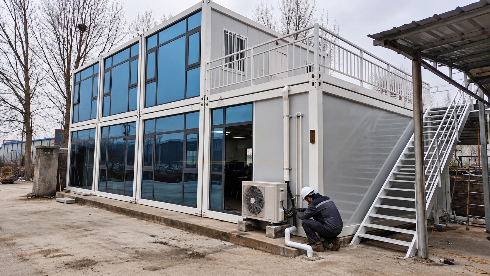
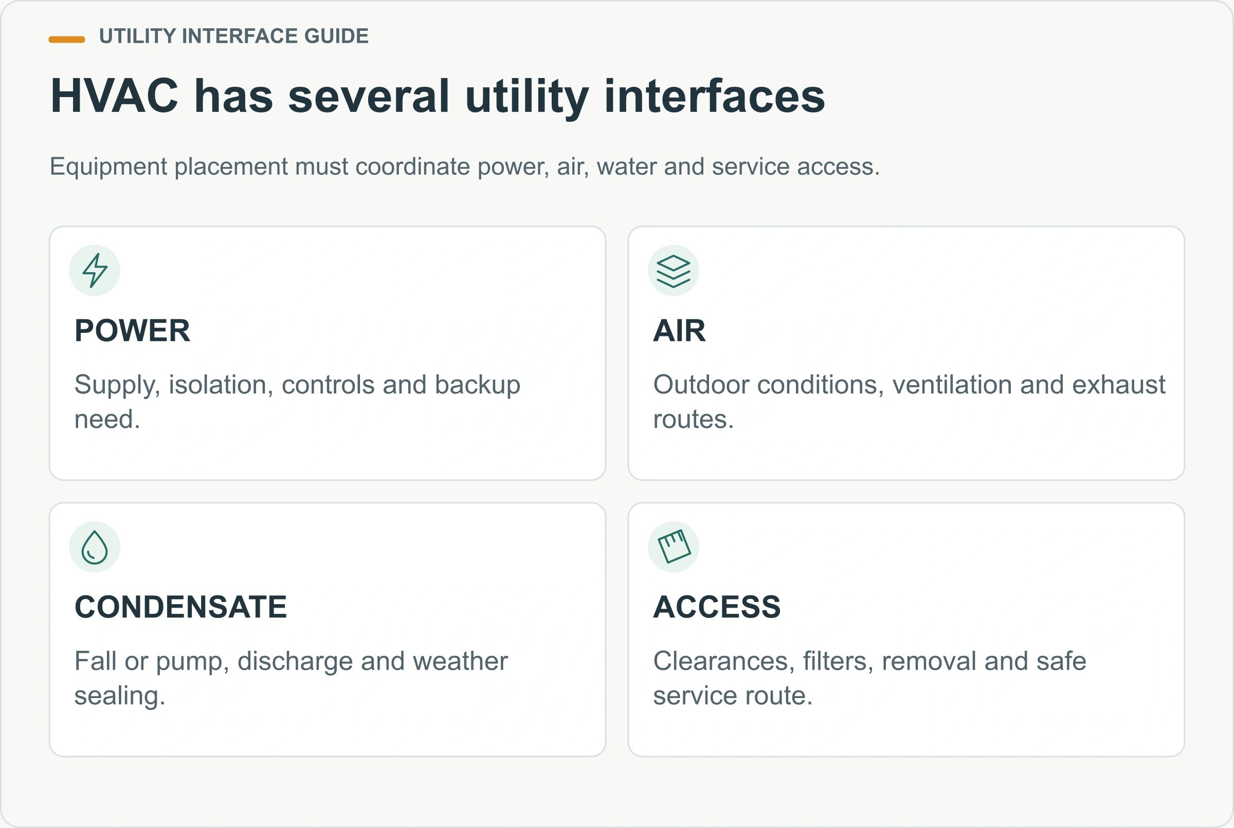
Record indoor and outdoor design conditions, ventilation requirement, selected system, equipment locations, clearances, outside-air and exhaust routes, condensate disposal and maintenance access. Avoid locating an outdoor unit where it blocks module connections, doors, service paths or lifting points.
Condensate is a utility interface. Show its route and approved discharge, provide required fall or pump arrangement, and prevent water from draining across entrances or structural supports. Coordinate sleeves and supports in the factory design. A site-installed hole through a completed panel can compromise weather sealing and finish quality.
Ventilation for toilets, kitchens, showers and occupied rooms needs defined intake and exhaust paths. Check separation from contamination sources and re-entry points under local requirements. If exhaust equipment depends on the permanent electrical supply, include it in commissioning and outage planning.
Divide factory scope and site scope line by line
Use a responsibility matrix for every utility component. Typical columns are: design input, engineering, supply, factory installation, transport protection, site installation, connection, inspection, test, certification and final record. Assign one responsible party to each action and name the reviewer or approver where necessary.
The container house kit inclusion guide helps distinguish supplied components from site work. Go further for utilities. For example, “electrical included” might cover internal lights and outlets but exclude the incoming cable, utility application, external trench, meter, earthing electrode and local certification.
Issue an interface drawing with a plan, elevation or section as needed. Give dimensions from stable reference points, not from movable furniture or unverified ground level. State connection orientation, size or type, access zone and identification. Provide coordinated openings rather than asking the site team to decide their location during installation.
Review logistics too. Loose valves, connectors, distribution components or commissioning spares need package identifiers and protection. The container house loading and shipping guide explains how packing records and receiving checks protect completeness through transport.
Control changes through the interface register
Every equipment or layout change should trigger an interface review. A larger water heater may change electrical load, pipework, weight and maintenance clearance. Moving a sink changes water, waste, cabinet and wall-penetration information. Adding an exterior light affects the panel, circuit, weather sealing and packing protection.
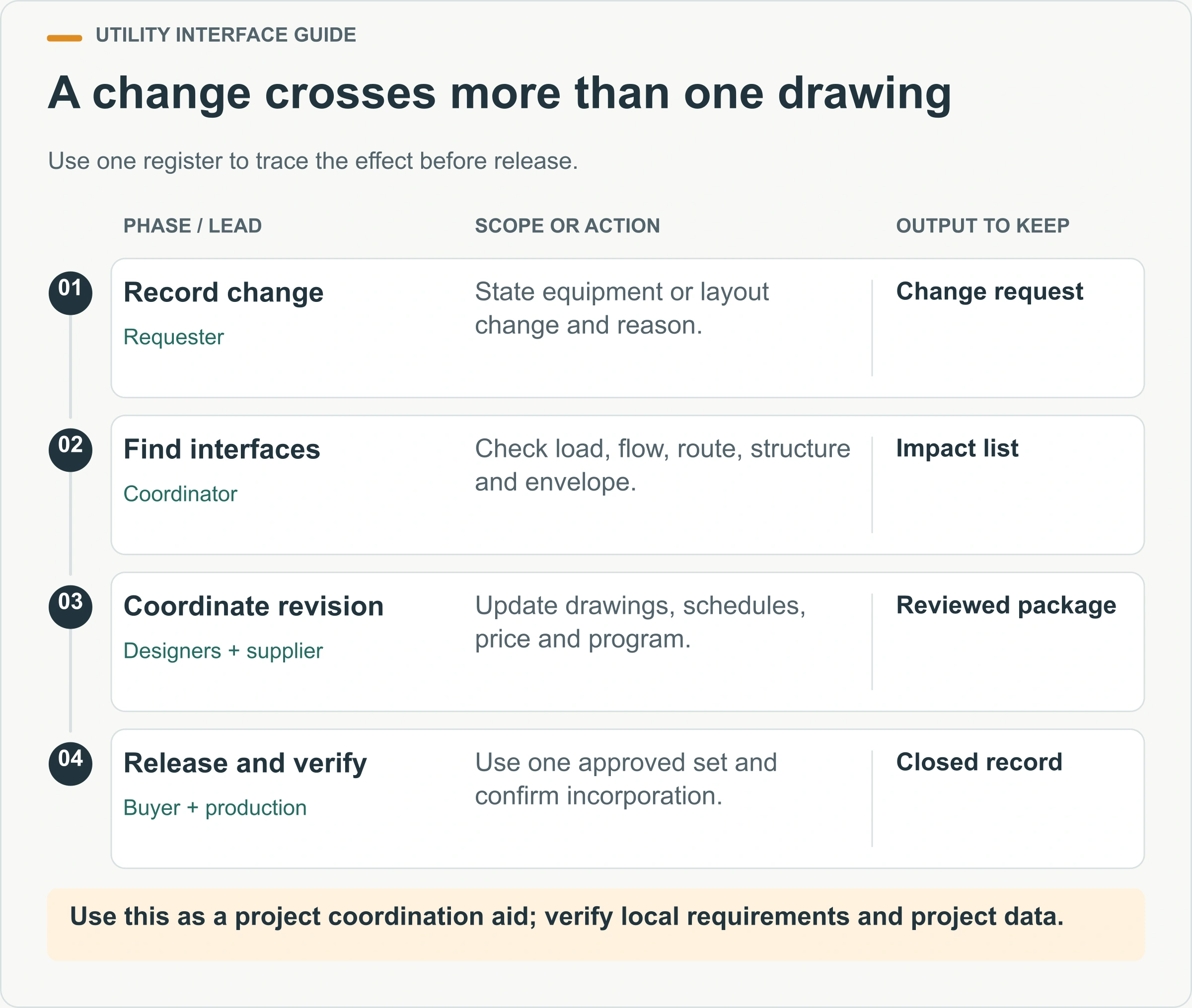
Use a change record with the request, reason, affected drawings, load or flow effect, structural and envelope effect, price and schedule. Mark the change as proposed, reviewed, approved, incorporated and verified. Do not release production from isolated markup files that have not been coordinated with the schedules.
Keep one master interface register. When a value changes, update the drawing and schedule references together. At design freeze, check that every interface has an owner and that provisional data has an action date. A blank value is safer than an invented one only when it is clearly controlled and prevents release of affected work.
Check the site before the factory layout is frozen
A desktop utility record needs a physical site check. Confirm the proposed module positions, orientation, support levels, access and the actual location of utility sources. Photograph and survey the relevant points with permission, and relate them to a controlled site plan. Note obstructions, buried-service information, overhead restrictions, flood or drainage paths and areas that must remain accessible.
Ask the utility owner or local contractor to confirm capacity and connection conditions in writing. An existing pipe or cable near the site does not demonstrate that it is available, suitable or authorized for the project. Record any application, upgrade or lead time required. Long utility lead times can control the opening date even when module production is complete.
Reconcile site and factory coordinates. Use agreed datums and finished levels for water and drainage points, foundation penetrations and external equipment. Check tolerances and decide where adjustment is permitted. Flexible connectors may accommodate limited movement, but they should not be used to disguise an uncoordinated location or unsupported pipe route.
Review how the installer reaches every connection after the modules are positioned. A connection shown between tightly spaced units may become inaccessible. Confirm the sequence for joining modules, making utility connections, testing, closing access panels and applying weather seals. Preserve access needed for future inspection and isolation.
The site check should end with an action list, not just photographs. Give each unresolved capacity, level, route or authority question an owner and due date. Prevent release of the affected production detail until the answer is incorporated into the interface register and coordinated drawings.
Commission from the source through the operating equipment
Commissioning should prove the complete installed path, not only individual components. Agree tests, instruments, acceptance criteria, responsible people and records before installation. Local requirements and manufacturer instructions determine the detailed procedure.
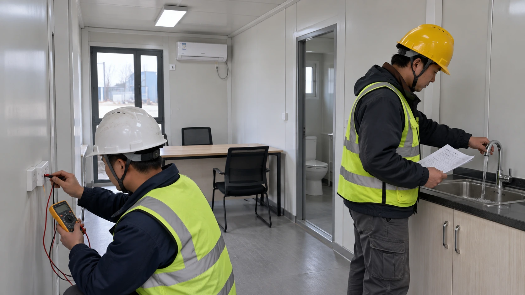
For electrical systems, the competent team may need to verify incoming conditions, connections, protective conductors, circuits, controls and equipment operation. For water and drainage, checks may include cleanliness, pressure or leakage, fixture operation, drainage performance and interfaces with tanks or treatment systems. HVAC checks should address power, controls, airflow, condensate and access.
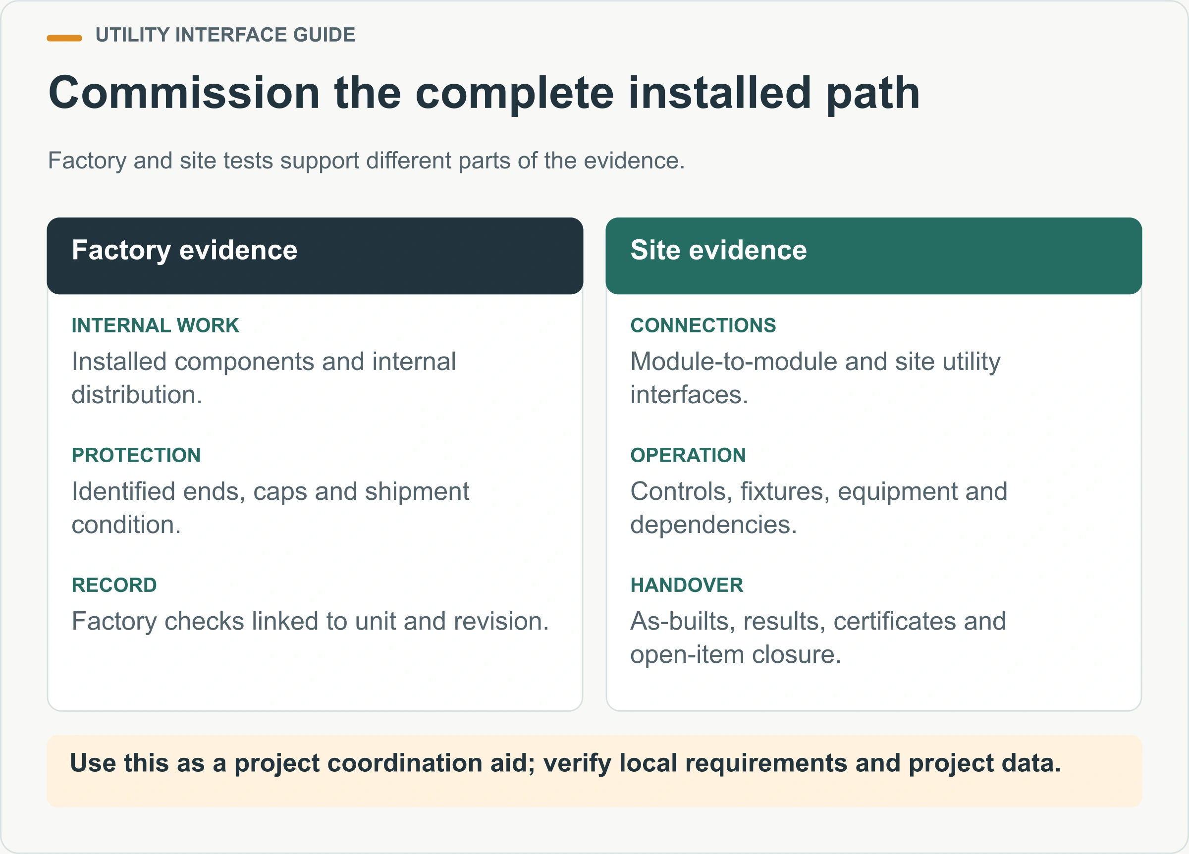
Record failures and corrective actions. Re-test the affected function and any related interface before closure. Keep as-built drawings, settings, test results, certificates, manuals, warranties, spares and service contacts in the handover file. The installation and handover guide provides a broader sequence from site readiness through acceptance.
Run a coordinated failure and capacity review
Test the plan against credible operating conditions before handover. Ask what happens when the permanent supply is delayed, a pump fails, a drainage route is blocked, a module connection is damaged or an HVAC unit is unavailable. Identify which spaces lose service, how the system is isolated and who authorizes restart.
Do not label every load “essential.” Work with the operator to identify genuinely critical functions and acceptable interruption periods. If backup power or stored water is required, define which circuits or uses it supports, its duration basis, changeover method, testing and maintenance responsibility. A generator on a product list is not a resilience plan.
Review expansion separately. Spare physical space in a panel does not prove the incoming supply or upstream infrastructure can support future modules. Record the assumed future load and confirm whether site mains, switchgear, water supply, drainage and treatment capacity are reserved for it.
Prepare the utility information package for suppliers
Give the supplier the destination, intended use, occupancy, climate data, operating hours, layout revision and equipment schedule. Attach confirmed utility information from the site and mark outstanding surveys. Identify the required local design and approval process without asking the manufacturer to guess compliance.
Request an interface register, coordinated service drawings, load and fixture schedules, connection details, component data, packing list, factory test plan and installation information. Ask the bidder to state exclusions and assumptions. Price optional equipment separately and keep the baseline comparable.
Require a deliverables register with document titles, responsible authors, review stages and planned issue dates. This is especially useful when the module supplier, local engineer, utility provider and site contractor work in different locations. It shows which information is needed before production, before shipment, before connection and before occupancy. During tender review, compare the proposed deliverables as carefully as the equipment list; missing drawings and test records can transfer coordination work to the buyer even when the physical components appear complete.
Use the container office product page when the building is an office, and consult the container house cost guide to carry utility connections, local trades and commissioning into the total project budget. Resolve destination requirements with the permits and codes planning guide.
When the layout, site utilities and connection responsibilities are available, send the project brief to PQSE House for configuration and factory-scope coordination.
At handover, store the approved interface schedule with current drawings, test records and equipment information. Give each unresolved item an owner and a completion condition. Where the site team changes a route or connection, update the record before the alteration is hidden by finishes or backfilling. This discipline helps operators understand what was installed and gives future maintenance teams a reliable starting point. It also separates a verified connection from a provisional allowance that still needs qualified local review.