PQSE HOUSE · PREFAB BUILDING SYSTEMS

Prefab K House
for Camps & Site Buildings

A prefabricated K house combines a light steel structure with insulated wall and roof panels. Its modular bay system supports repeated rooms, offices, classrooms and shared camp buildings. Start with the room arrangement and module dimensions, then coordinate access, services and the complete supply scope.

UNDERSTAND THE SYSTEM

What Is a Prefab K House?

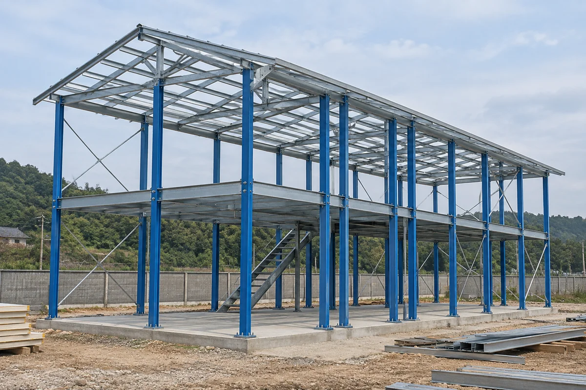
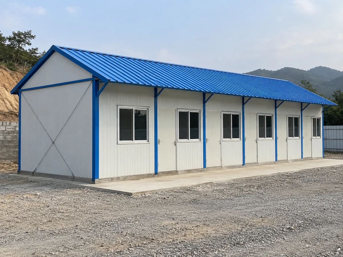
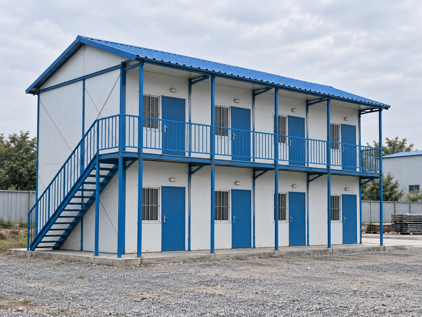
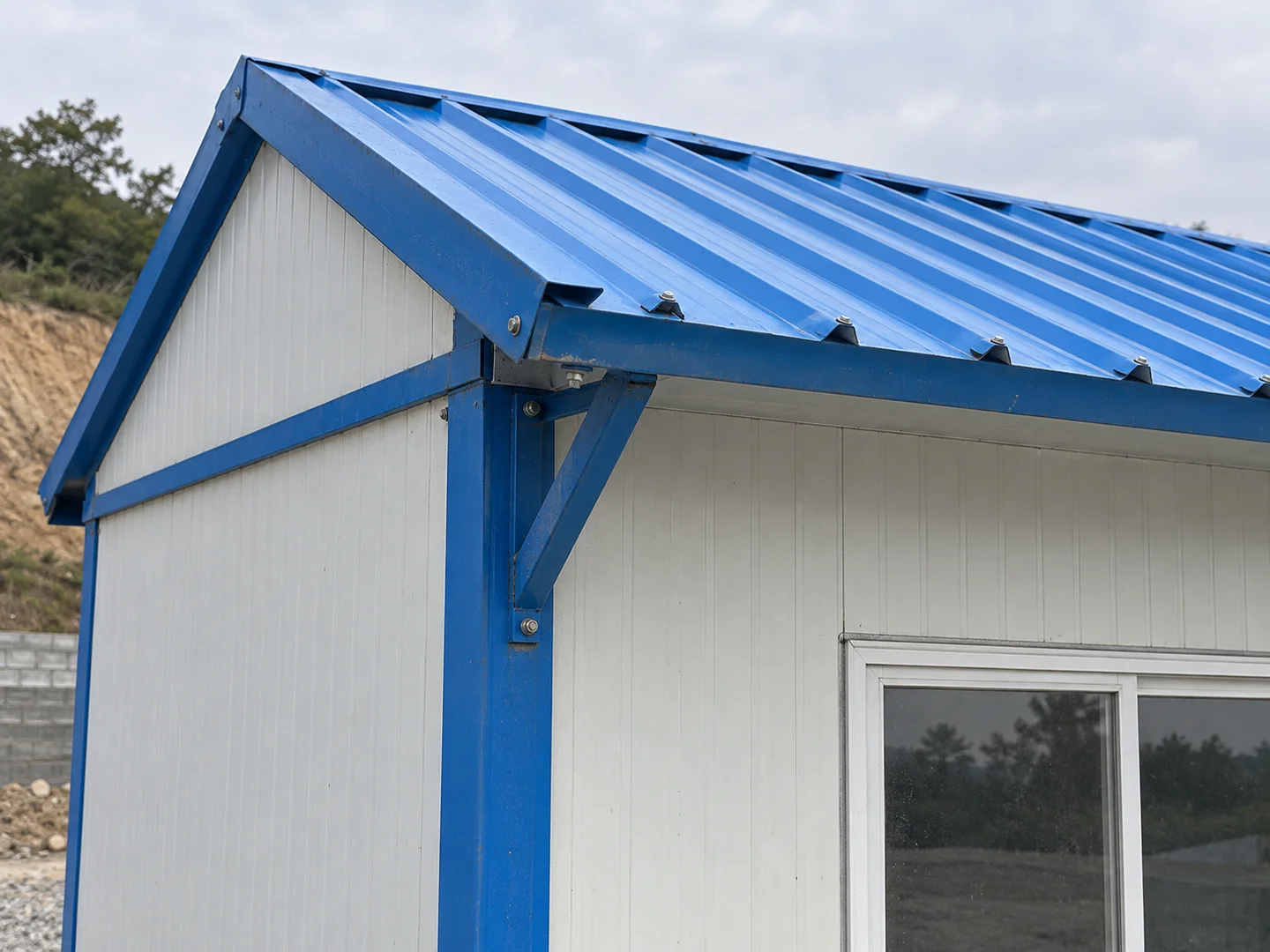
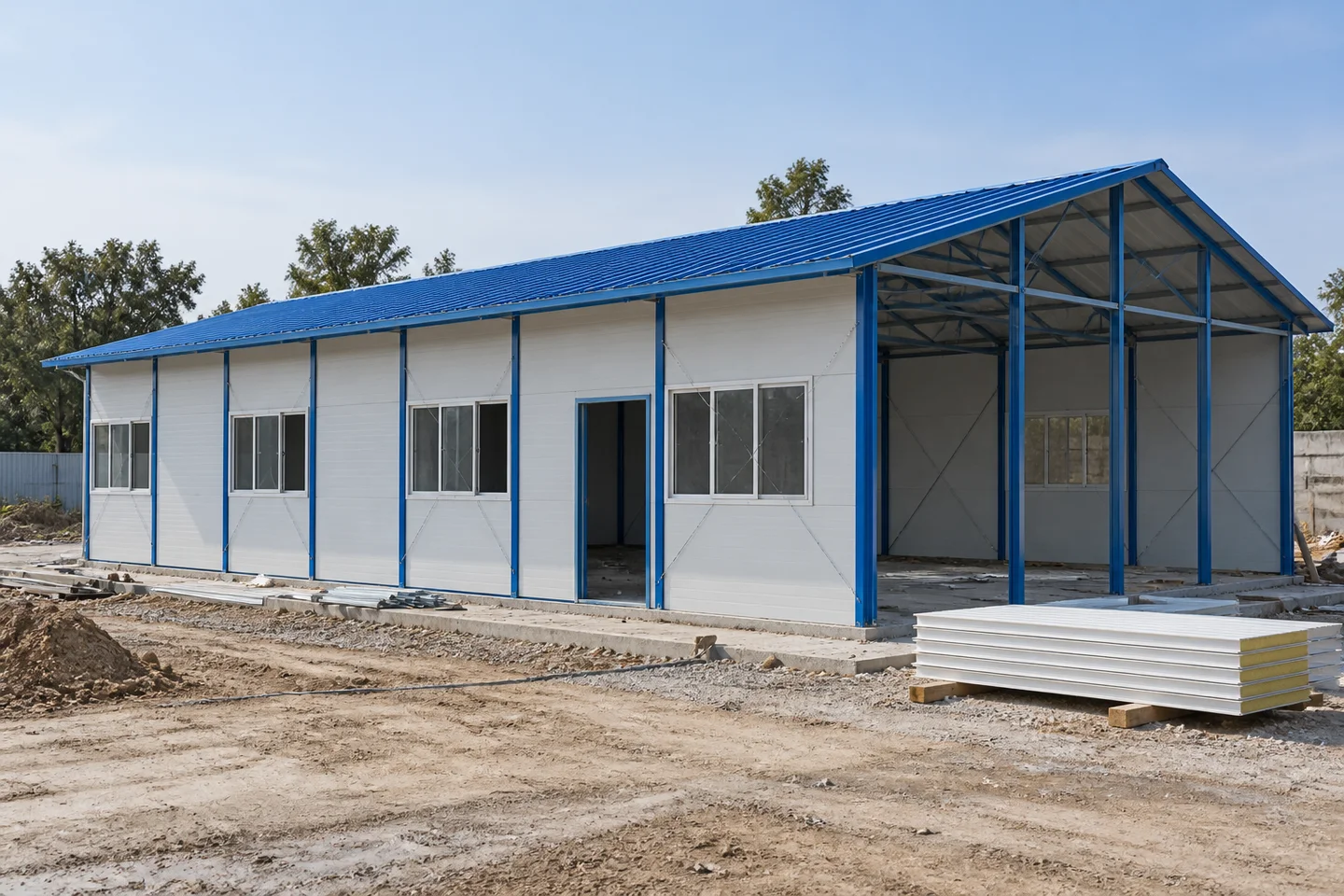
A prefab K house has a light steel frame and panel walls. The parts are assembled on site. Repeated frame sections set the building length and room layout. Its pitched roof gives it a different shape from a container room.

Plan the frame, roof, walls, doors and site connections together. The building needs to work as a whole, as well as look right.

A useful starting point when

Compare another system when

BUILDING OPTIONS

Choose the Building Arrangement First

Start with the site area, room count and building use. The number of floors affects access, ground work and the frame design.

01 / ONE LEVEL

Single-Storey K House

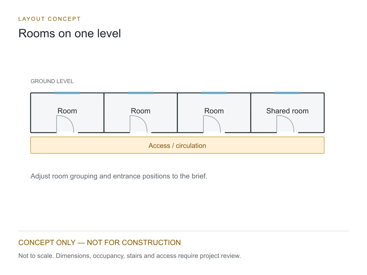
A single-storey layout keeps all rooms and entrances at ground level. It can suit offices, living quarters and shared facilities when the site has enough space.

building footprint; room grouping; entrances; service connections.

02 / TWO LEVELS

Two-Storey K House

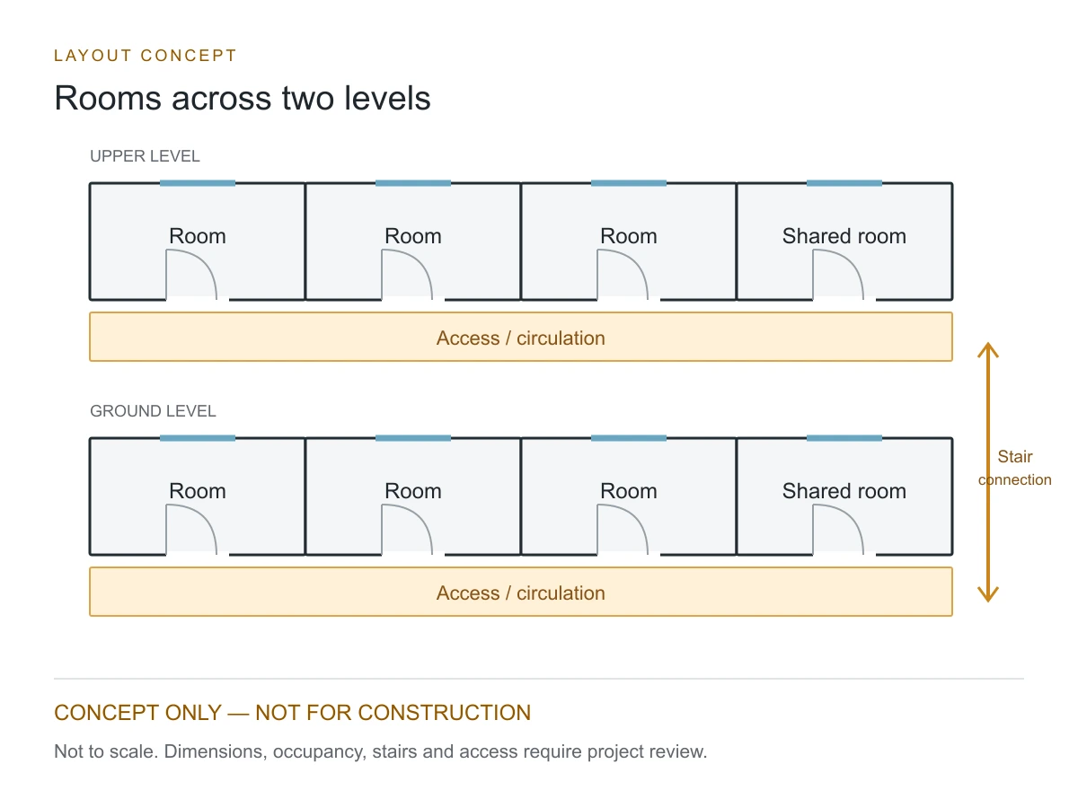
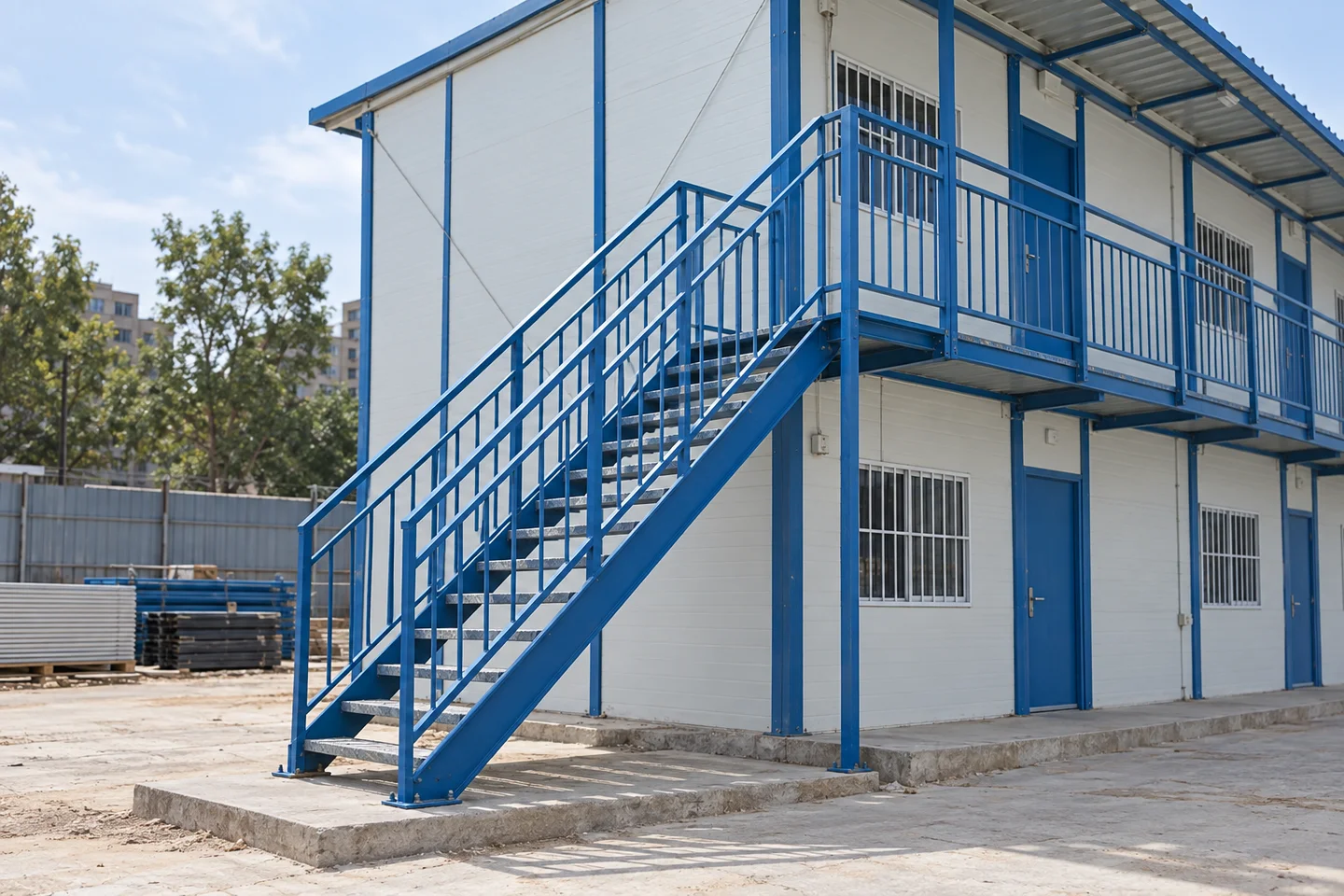
Two floors can provide more space on a small site. Review the upper floor, stairs, corridors and foundations together, and confirm local approval and building-use requirements with your project team before agreeing the layout. Suitability must be assessed for the proposed K-house system and site.

approved structural arrangement; stairs and circulation; foundation interface; permitted use.

ROOMS & CIRCULATION

Plan Rooms, Access and Shared Spaces Together

A practical layout connects room use with entrances, circulation, storage and supporting facilities. For workforce accommodation, establish room mix, shift routines and shared facilities before converting the brief into repeated K-house structural bays.

Share the number of people or rooms, the usable site area and any existing plans. These inputs help establish the room arrangement before materials and supply details are finalized.

Floor Plans and Configuration Data

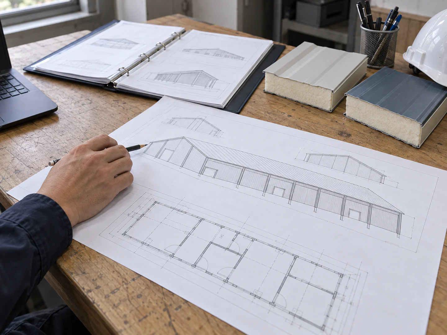
Choose a layout by its room arrangement and the data shown beside it. Furniture and fittings are layout references; final details follow the selected drawing.

Layout reference. Read the stated dimensions; internal clearances and service positions follow the approved project drawing. Select image to enlarge.

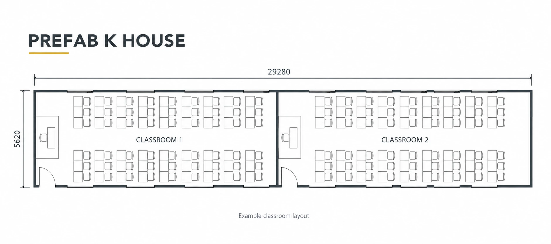
Two-classroom building

Drawing dimensions

29,280 × 5,620 mm.

Rooms shown

2 classrooms.

Planning grid

K = 1,820 mm; finished dimensions follow this specific drawing.

Layout reference. Read the stated dimensions; internal clearances and service positions follow the approved project drawing. Select image to enlarge.

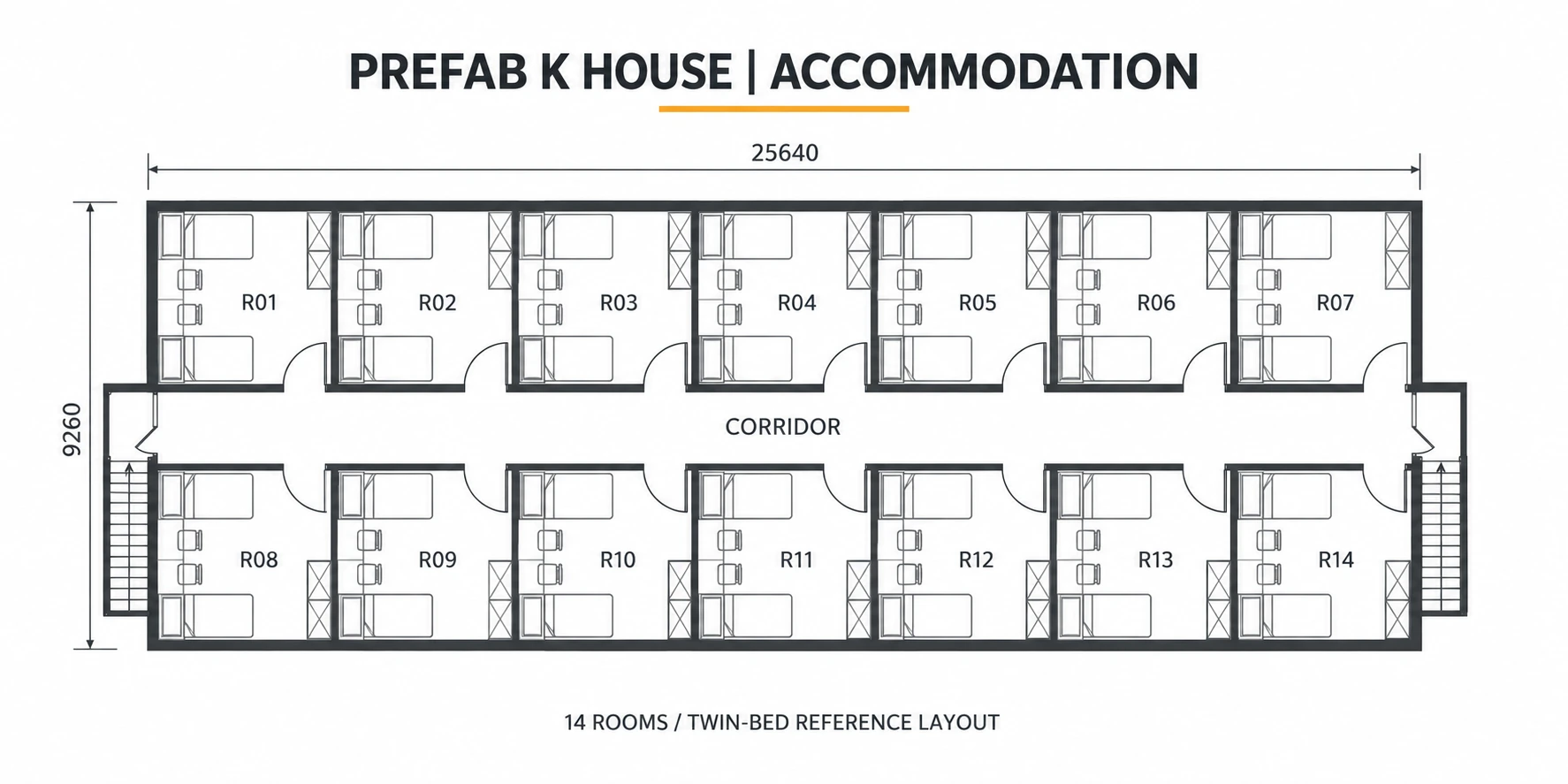
Accommodation floor · 14 rooms

Drawing dimensions

25,640 × 9,260 mm, excluding external stairs.

Rooms shown

14 rooms in two rows of 7.

Beds shown

2 beds per room; 28 bed positions in this example.

Access

Central corridor with stairs at both ends.

Layout reference. Read the stated dimensions; internal clearances and service positions follow the approved project drawing. Select image to enlarge.

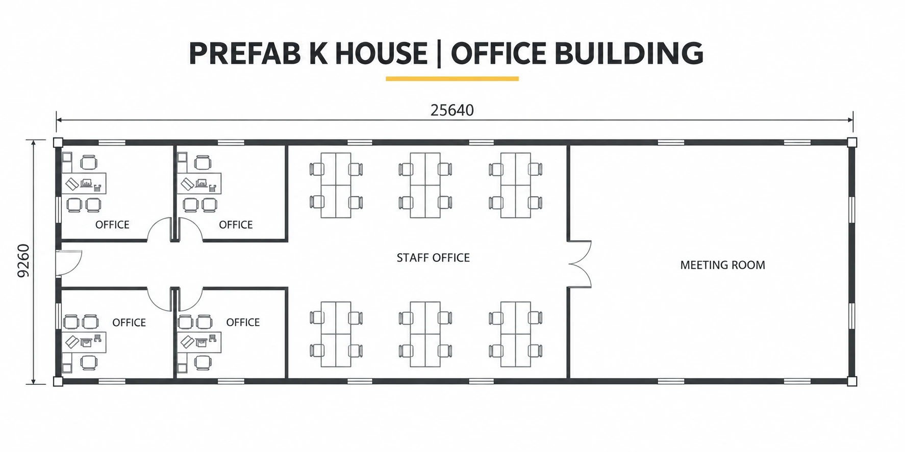
Office and meeting-room building

Drawing dimensions

25,640 × 9,260 mm.

Private offices

4 separate offices.

Shared spaces

Open staff office and a large meeting room.

Planning grid

1,820 mm K-module bays; overall dimensions follow this drawing.

Concept A — Ground-Level Room Arrangement

Repeated rooms with direct access can support an organized accommodation or office brief. Entrance positions and shared facilities should be considered together with the site layout.

Concept B — Two-Storey Arrangement

Review the relationship between ground-floor rooms, upper-floor rooms, stairs and corridors. Confirm access requirements and structural feasibility before fixing the room count.

MATERIALS & SPECIFICATION

Prefabricated K House Module and Material Specifications

The K-type system uses K = 1,820 mm horizontally and P = 950 mm vertically. Before fixing the finished width, length and floor count, translate the planning grid into usable room dimensions; then specify the frame, panels, openings and external access. The classroom drawing below is a separate 29,280 × 5,620 mm example.

See the full specifications · View the floor plan

01

Structure and Connections

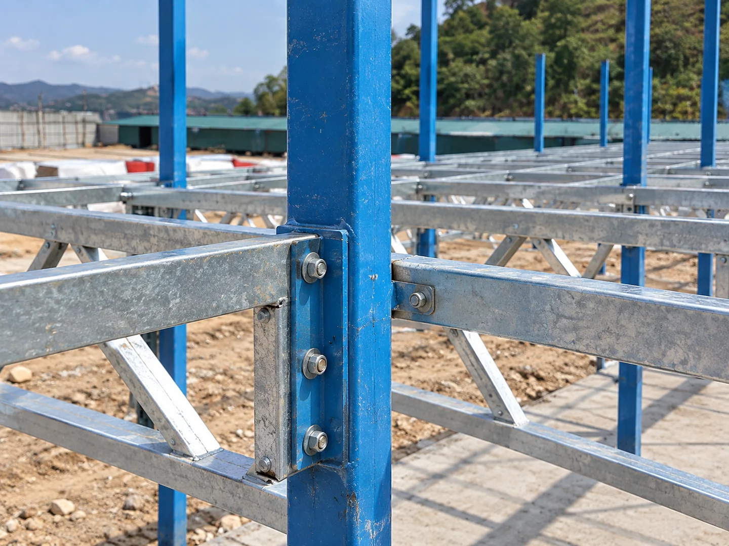
Review the frame and connection details against the intended building arrangement. A general product image does not establish structural capacity for your site.

02

Wall and Roof Enclosure

Panel selection should reflect the building use, climate and applicable requirements. Confirm the complete enclosure specification, not only a panel thickness.

03

Floors, Stairs and Access

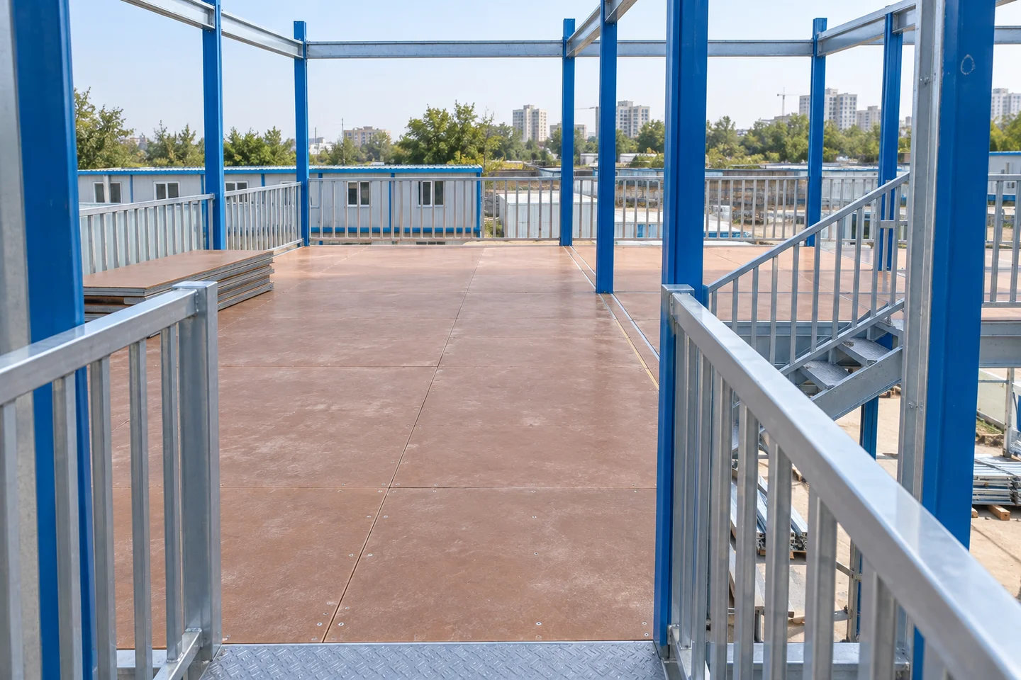
For an upper-floor arrangement, coordinate the floor system and external access as part of the building proposal. Do not treat these items as interchangeable accessories.

Key specification
Reference model
Horizontal module K
Reference model

1,820 mm

Vertical module P
Reference model

950 mm

Finished width range
Reference model

2K: 3,790 / 3K: 5,610 / 4K: 7,430 / 5K: 9,250 mm

Building levels
Reference model

One- and two-storey reference layouts; a three-storey proposal needs separate product and structural review

Models, Materials and Full Specifications

Compare the illustrated model or package with its complete specification. Dimensions are in millimetres unless stated; optional materials and equipment follow the selected order.

Product detail illustration; supplied components follow the selected specification. Select image to enlarge.

Building modules and width choices

Horizontal module K

1,820 mm.

Vertical module P

950 mm.

2K / 3K finished width

3,790 / 5,610 mm.

4K / 5K finished width

7,430 / 9,250 mm.

Length planning

Extend the building by K-module bays; final external length follows the building drawing.

Minimum reference module

3K × 2K × 3P; this is a building module, not an order quantity.

Product detail illustration; supplied components follow the selected specification. Select image to enlarge.

Frame, roof and wall system

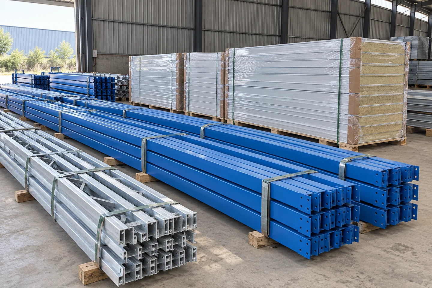
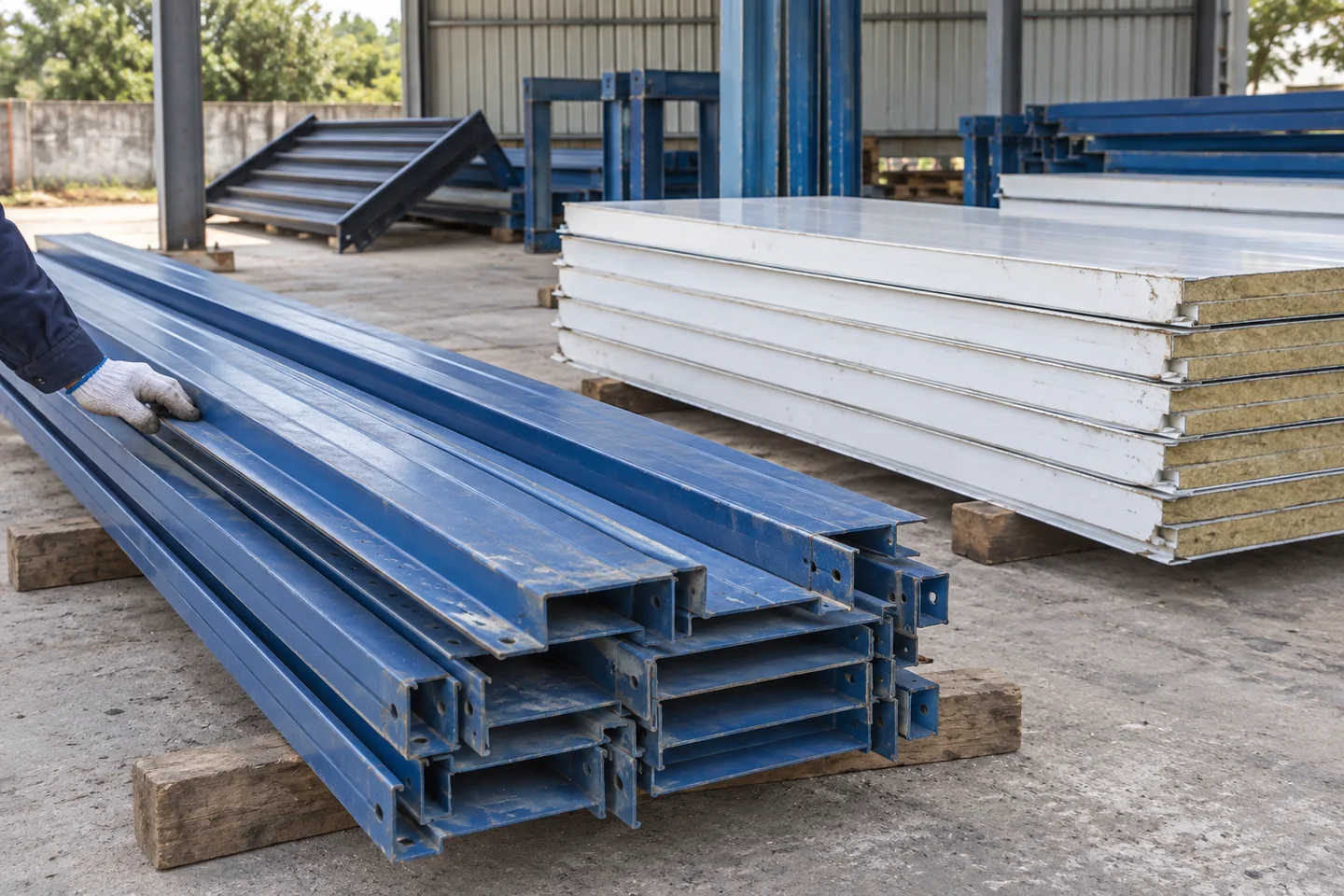
Main steel members

C-section purlins, channel steel and square tubes.

Wall panels

50 mm sandwich-panel reference.

Roof panels

50 mm sandwich-panel reference.

Insulation core options

EPS, polyurethane, rock wool or glass wool.

Partitions

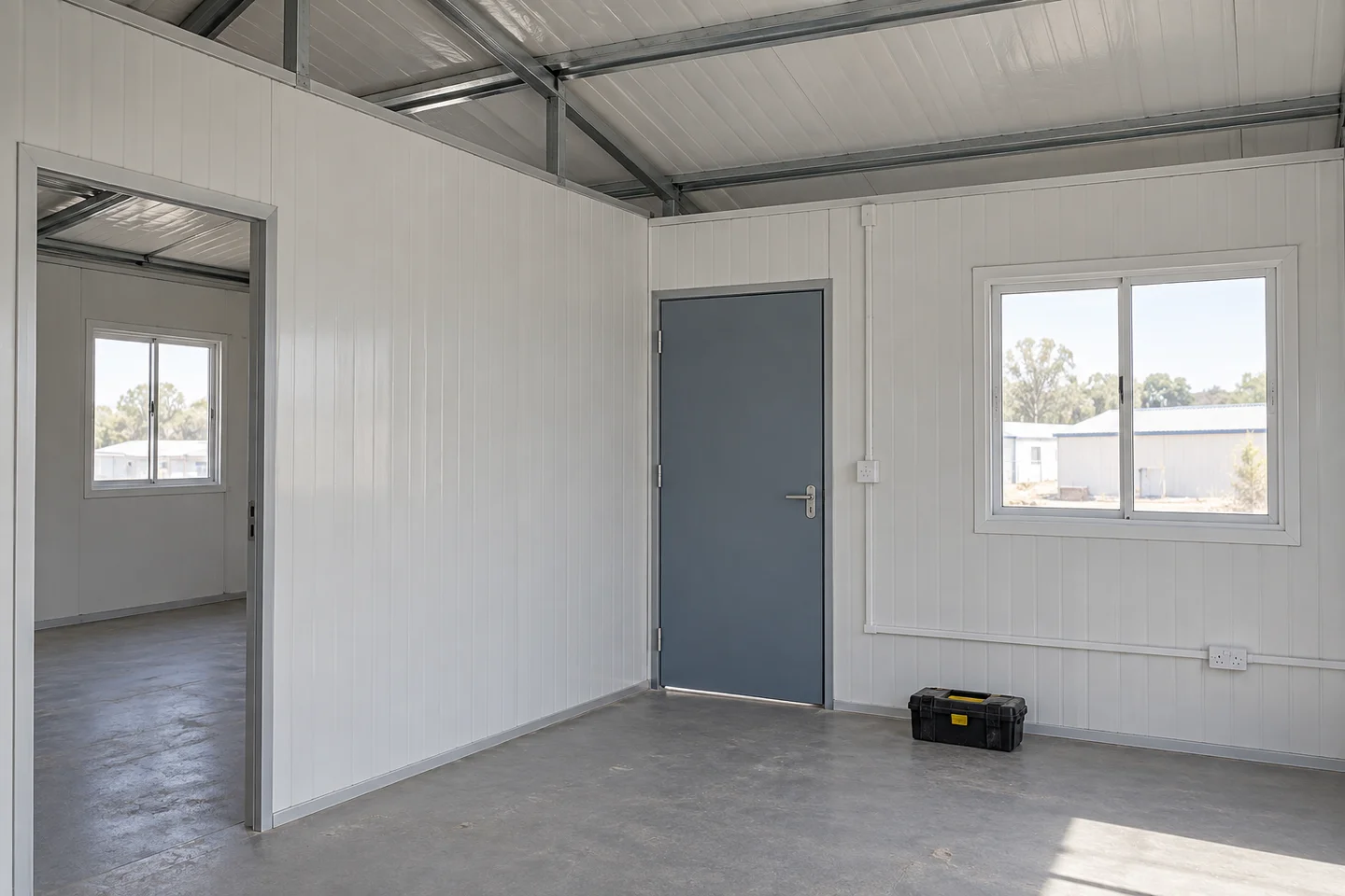
Lightweight sandwich panels divide the open building into rooms.

Connections

Bolted main structure; panels and finishes fixed with the specified fasteners.

Product detail illustration; supplied components follow the selected specification. Select image to enlarge.

Storeys, access and openings

Storey options

1, 2 or 3 storeys, subject to the structural and access design.

Walkway board

1.8 mm patterned steel plate in the published walkway package.

Door options

Steel security, aluminum alloy, thermal-break aluminum or stainless steel.

Windows

Positions are coordinated with the room bays and daylight needs.

Stairs and railings

External stairs, walkways and guardrails form part of the multi-storey package.

Product detail illustration; supplied components follow the selected specification. Select image to enlarge.

Layouts, appearance and site inputs

Classroom drawing

29,280 × 5,620 mm overall; this drawing uses its own finished dimensions.

Illustrated rooms

2 classrooms with shared circulation planned around the entrances.

Other building functions

Offices, accommodation, dining rooms and shared facilities.

Color options

Blue, white or red in the published finish range.

Site coordination

Building layout, foundation, drainage, local wind/snow loads and access determine the final project details. Identify the site-specific design basis and supporting engineering evidence; the responsible professionals must assess the actual K-house system rather than transfer a rating from another building.

SPACES THAT WORK

Match the Interior to the Daily Task

Worker Accommodation

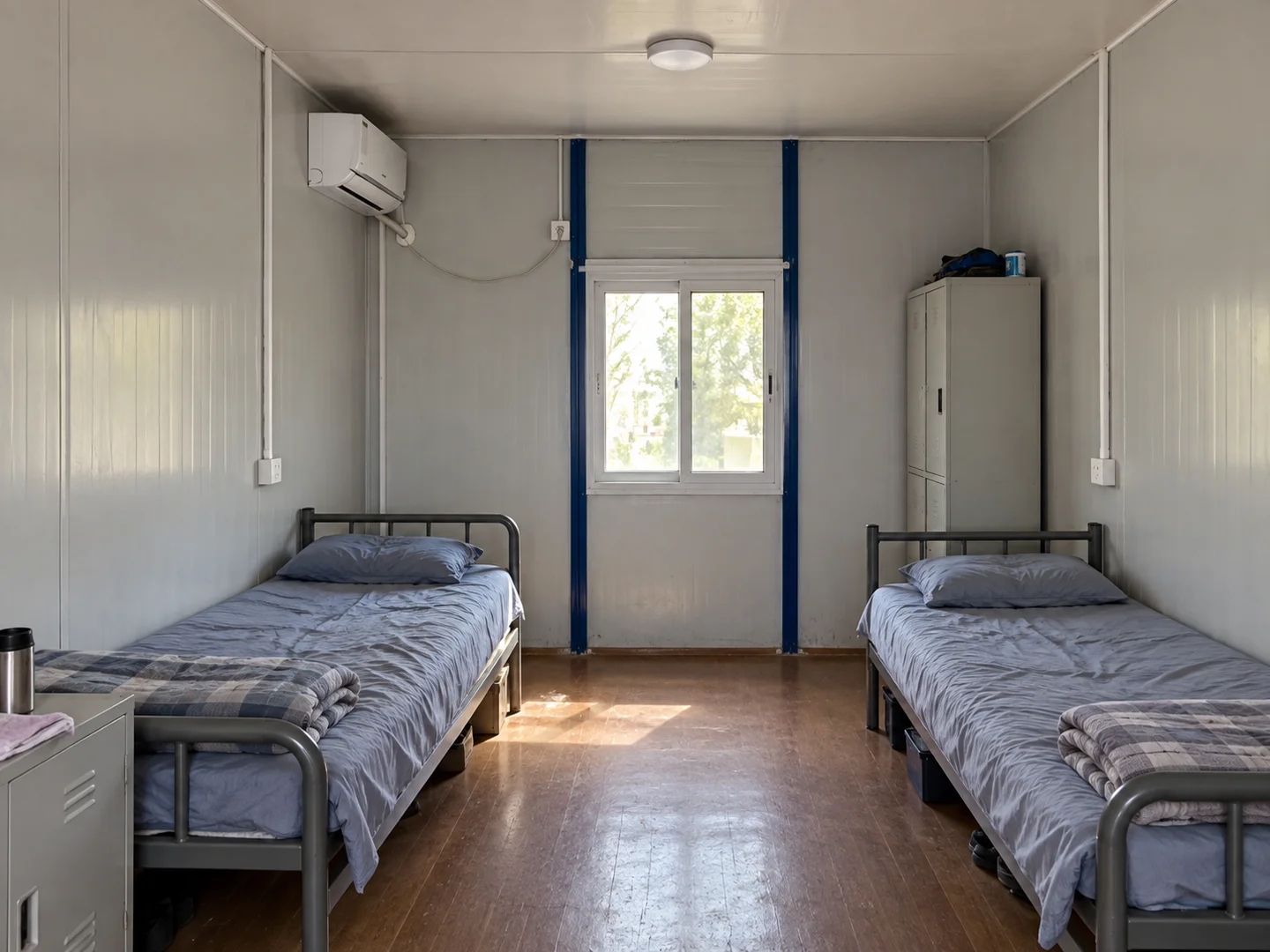
Plan sleeping areas, personal storage and circulation around the intended occupancy. Confirm ventilation and the relationship to toilets, showers and shared facilities before fixing the layout.

Site Offices

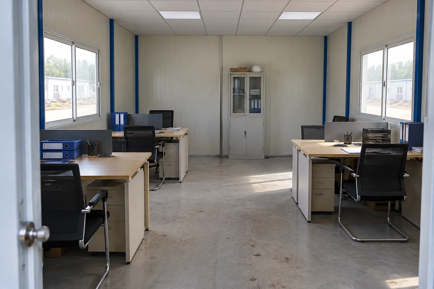
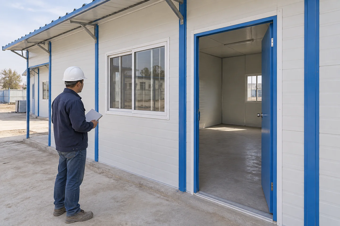
Organize workstations, meeting space and visitor access for daily site coordination. Review lighting, electrical positions and communications requirements as part of the fit-out brief.

Dining and Shared Facilities

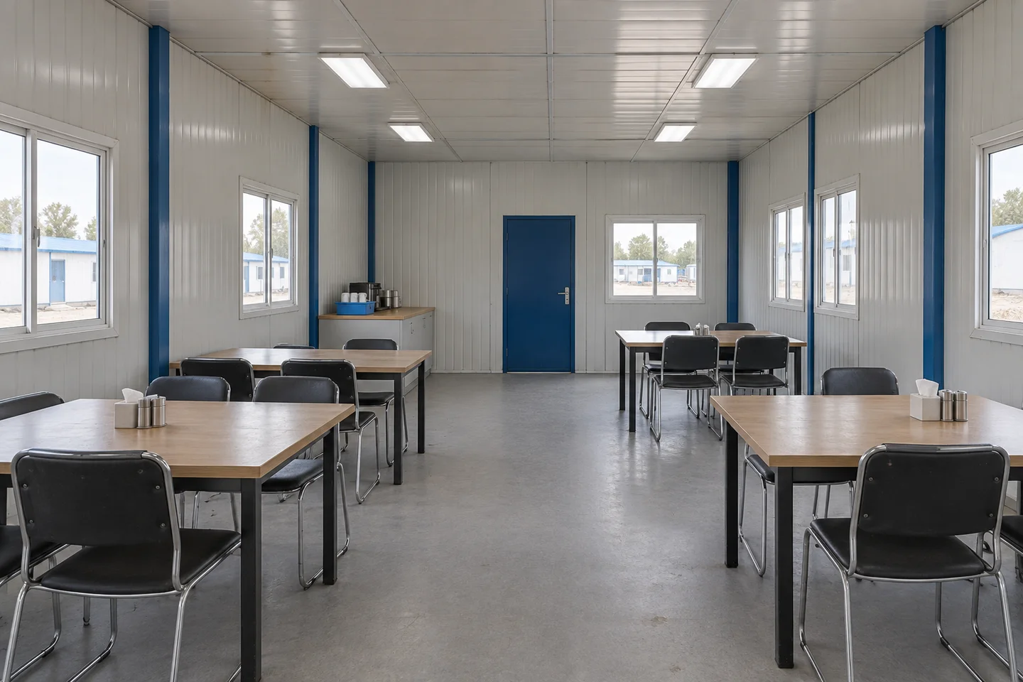
Consider seating, serving and cleaning routes together with the available utilities. Cooking equipment, extraction and any specialist requirements need a separate, clearly agreed scope.

SUPPLY & RESPONSIBILITIES

Make the Supply Scope Clear Before Ordering

Two proposals are only comparable when they describe the same scope. Use the quotation and approved documents to identify the building package, any fit-out additions and the work to be arranged on site.

01

Building Package to Confirm

Steel frame members and connections; wall and roof components; doors and windows; applicable floor and access components; agreed fasteners and finishing details.

02

Fit-Out Options to Discuss

Internal partitions, electrical scope, ventilation or air-conditioning, sanitary facilities and other project-specific additions. Availability and interfaces are confirmed in the proposal.

03

Site Responsibilities to Allocate

Foundation and anchoring interfaces, unloading, storage, installation resources, utility connections, local approvals and final acceptance arrangements.

SITE READINESS

Confirm the Site Before the Building Ships

The site plan should be coordinated with the building proposal before dispatch. Early clarification helps identify work, equipment and information needed for assembly.

01

Foundation and Building Interface

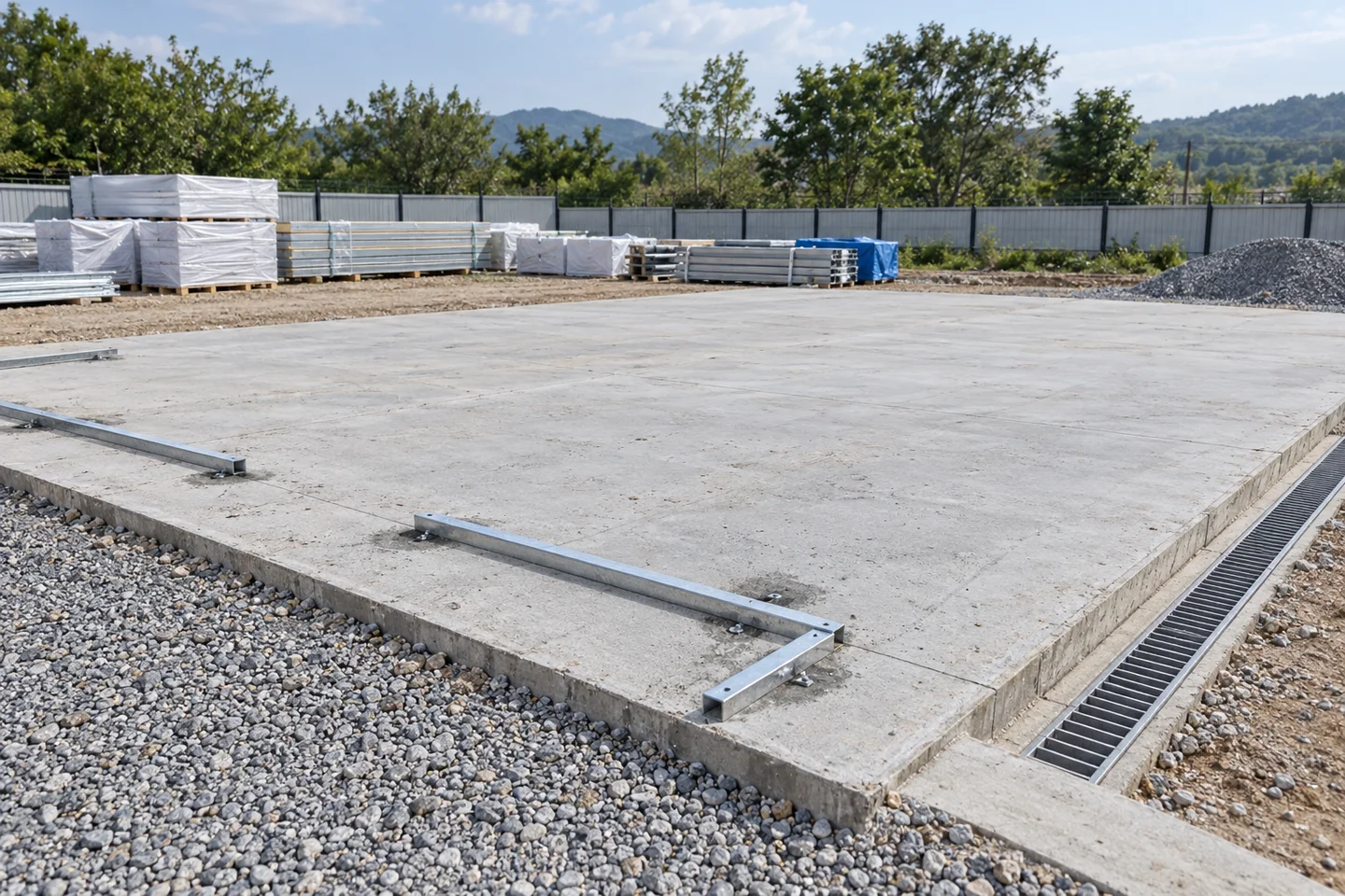
Provide available site and ground information. The foundation and anchoring solution must be established for the actual building and site by the responsible project professionals.

02

Drainage and Weather Exposure

Review surface water, roof drainage and surrounding levels with the site design. Product photographs cannot confirm the suitability of a drainage arrangement.

03

Access, Unloading and Storage

Check delivery access, unloading arrangements and protected storage areas for components. Plan material handling around the site conditions and agreed installation method.

04

Utilities and Installation Resources

Confirm the service connection points, local installation responsibilities and supporting equipment before the work begins.

ON-SITE ASSEMBLY

From Packed Components to an Enclosed Building

These stages explain the coordination involved in site assembly. The approved drawings, installation documents and site method determine the actual work sequence and required precautions.

01 / 06

Receive & Check Components

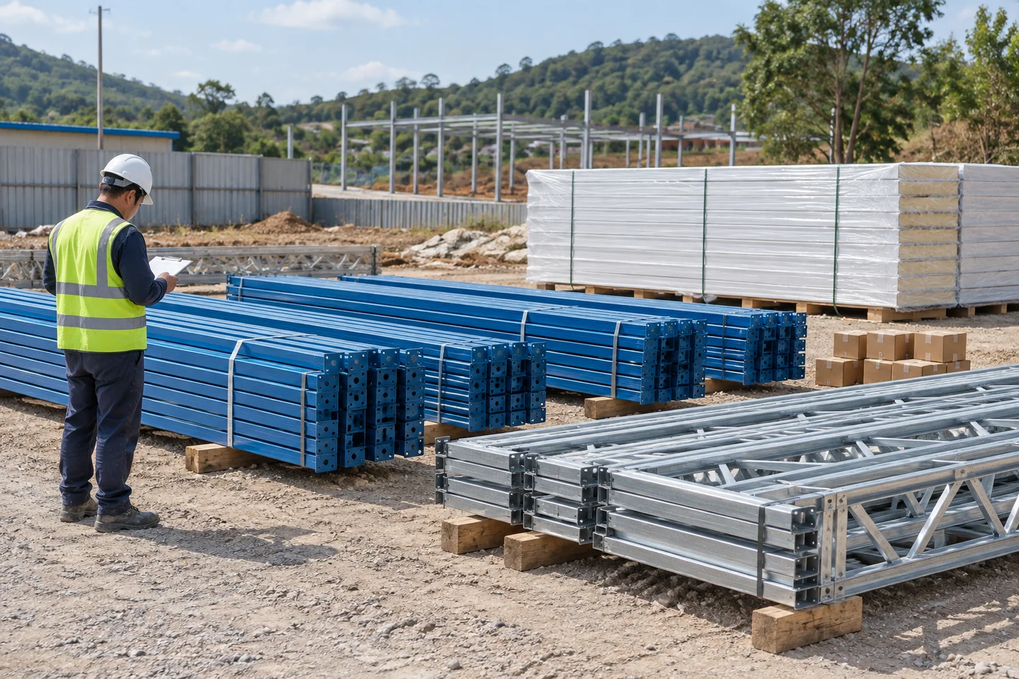
Match delivered items to the packing information and identify anything damaged or missing before assembly proceeds.

02 / 06

Set Out & Assemble the Frame

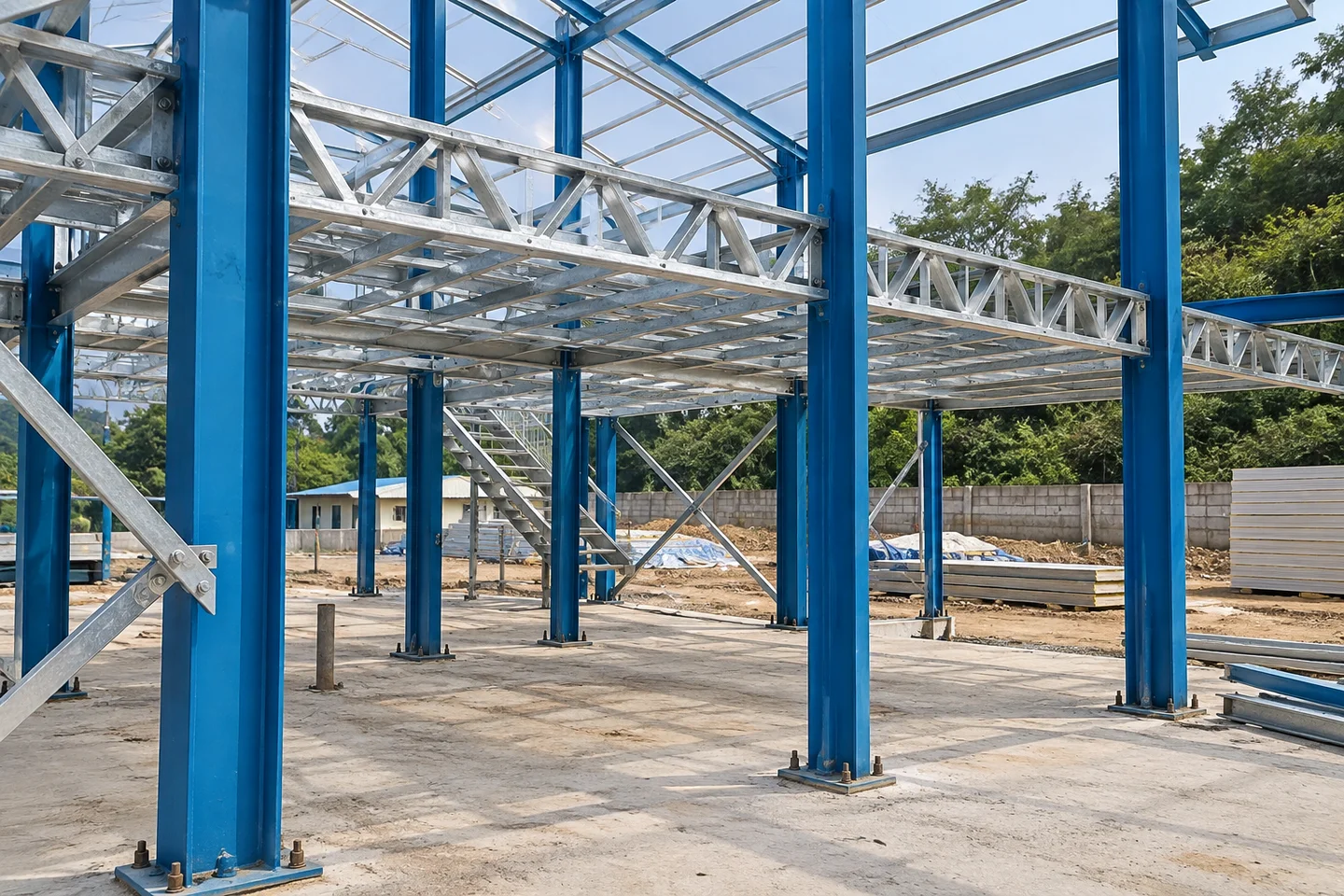
Coordinate setting out and structural assembly with the approved foundation interface and building documents.

03 / 06

Complete Floors & Access

Install the agreed floor and access components where applicable. A two-storey arrangement requires coordinated upper-floor and access work.

04 / 06

Close the Roof & Walls

Complete the specified enclosure and associated joints, trims and weather details according to the approved documents.

05 / 06

Fit Openings & Services

Complete doors, windows and the agreed fit-out or service work. Confirm any interfaces with equipment or work supplied by others.

06 / 06

Inspect Before Handover

Review the finished scope, record outstanding items and confirm the relevant operation and maintenance information.

LOGISTICS & RELOCATION

Plan Packing, Storage and Future Reuse

Component Packing

A K-type building is planned around a coordinated component package. Confirm item identification, protection, packing information and unloading needs for the agreed order.

Shipping quantity and loading arrangements depend on the actual component list and packing plan. A sample package photograph does not establish a standard container capacity.

Future Dismantling and Reuse

If relocation is part of your project, raise it during the initial brief. Reuse depends on the building design, component condition, dismantling method and requirements at the next site.

Allow for inspection, replacement of unsuitable items, new site preparation and installation work. Reuse should be assessed as a project decision, not assumed to be loss-free or unlimited.

COMPARE THE SYSTEMS

K House or a Container-Based System?

Compare the building system with the work you can organize on site. Product names alone do not tell you the complete delivery or installation scope.

Structural concept
Prefab K House

Bay-based frame with a separate pitched roof and panel enclosure

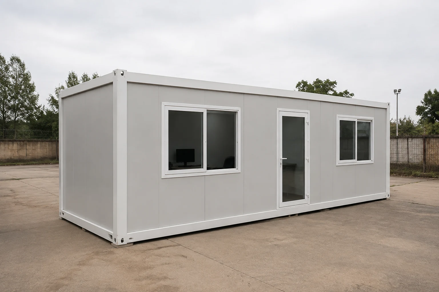
Container-format room system using a coordinated frame and enclosure package

Container-format system assembled from separate frame and enclosure components

Planning emphasis
Prefab K House

Building footprint, repeated bays, rooms and circulation

Room modules, their arrangement and connection interfaces

Component-based room assembly and the proposed module arrangement

Supply information
Prefab K House

Building drawings and coordinated component list

Confirm the frame/floor/roof package and factory completion level

Confirm the member, panel and connection package

Site work
Prefab K House

Coordinate foundation, structure, roof, enclosure and applicable fit-out

Coordinate preparation, handling, assembly and the remaining fit-out

Coordinate component identification, assembly and the remaining fit-out

Best next step
Prefab K House

Review site area, storeys and room plan

Review module layout and delivery scope

Review assembly resources and component scope

PROJECT DOCUMENTS

Review the Documents Behind the Proposal

Start with the model specifications and floor-plan reference on this page. The related planning guides explain layout, materials or building-package preparation. For order-specific drawings and supply details, send your project requirements.

01

Layout & specification

The agreed building arrangement and product scope.

02

Components & packing

The items and identification used for the order.

03

Material & test information

Documents relevant to the specified materials and requirements.

04

Assembly & maintenance

The guidance available for the agreed building package.

COMMON QUESTIONS

Prefab K House Questions, Answered

In the reference system shown here, K is a 1,820 mm horizontal planning module and P is a 950 mm vertical module. Finished external dimensions depend on the selected drawing and enclosure details. See the module and finished-width references; do not substitute a bay count for the building dimensions.

A K house is organized as a frame-and-panel building with a separate pitched roof. A flat pack container house is a container-format room system. Compare their supplied components, room planning and site work rather than relying only on the product name.

A two-storey arrangement can be considered during project review. Feasibility depends on the available product system, structural design, foundations, access arrangement, intended use and applicable local requirements. Do not assume that an existing single-storey building can simply receive another floor.

The preparation scope normally needs to address the foundation interface, drainage, delivery access, unloading and storage, utilities and installation resources. Confirm the responsibilities with the project team before dispatch. This page does not prescribe a universal foundation design.

The programme depends on building size, storeys, fit-out, site readiness, installation resources, equipment and weather. Request a programme based on the agreed scope rather than a generic daily installation rate.

Potential reuse must be reviewed against the design, condition of the components and requirements at the next site. Dismantling can damage panels, connections and finishes, so inspection and replacement allowances should be considered in the relocation plan.

Provide the destination, intended use and relevant project requirements at the brief stage. Review the complete proposed material and building system, together with applicable evidence. A panel label or a general company certificate does not establish the performance of every building configuration.

Send the destination, application, preferred storeys, required rooms or occupancy, available site area and any drawings. Include material, local performance, fit-out and delivery requirements where known. The proposed scope, commercial terms and programme are confirmed individually.

PRODUCT CUSTOMER REVIEWS

Prefab K House Reviews

5 / 5 based on 3 customer reviews. Read their experiences with this product.

5 / 5

The dormitory layout makes sense in daily use

We started by discussing how the accommodation would be managed, not just how many rooms we wanted. The room arrangement and circulation were then worked through with PQSE. Once in use, the layout has been straightforward for both residents and the housekeeping team. I am glad we spent time on those details. It is a sensible solution for what our camp needed.

Samuel Boateng
Workforce Accommodation Manager
Ghana

Project: Dormitory planning for a construction camp
Focus: Room organisation and circulation
5 / 5

A quotation we could actually compare with the plan

I needed to explain the proposed specification to our project team, including what was supplied and what remained site work. The quotation discussions made those distinctions clear. We could compare options without losing track of the original requirements. The chosen arrangement covers our needs without unnecessary additions. Both the building solution and the way the purchase was handled left a good impression.

Arun Menon
Quantity Surveyor
United Arab Emirates

Project: Office and accommodation support for a project
Focus: Quotation clarity and specification choices

5 / 5

Helpful handover for a busy site team

There were several people involved in preparing our site, so having an agreed layout and clear supporting information was important. PQSE's responses helped us resolve questions by referring to the relevant part of the plan. The rooms now provide a useful base for daily coordination. Nothing overly complicated, just an arrangement that suits the project and a team that was helpful to work with.

Paolo Villanueva
Construction Site Coordinator
Philippines

Project: Management offices and staff support rooms
Focus: Useful documentation and coordination

Let's Plan Your K House Project

Tell us where the building will be used, what spaces you need and which site conditions are already known. Share your room layout or project brief so the next discussion can focus on the proposed configuration and supply scope.

Suzhou, Jiangsu, China

Manufacturing and project support office.

Request a Project Quote